3
en
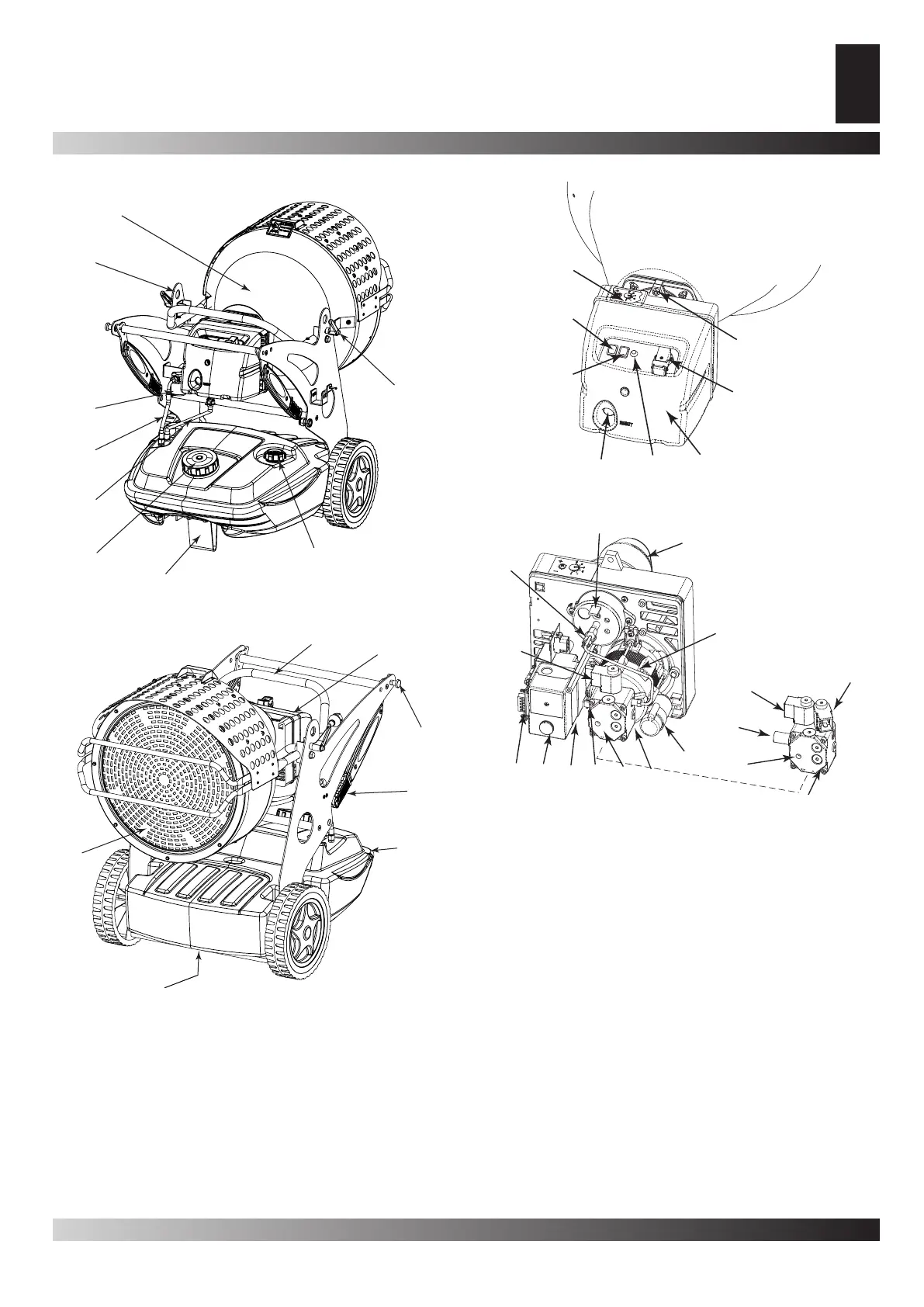
PRODUCT IDENTIFICATION
A. Combustion chamber, B. Hole for raising generator, C. Fuel
lter or pre-heated lter (optional), D. Fuel supply, E. Fuel Re-Fuel Re-
turn, F. Fuel tank cap, G. Foot or wheel (optional), H. Fuel level
indicator, I. Block of the group combustion, L. Radiant deector,
M. Fuel drain plug, N. Fuel tank, O. Handle to move the genera-Handle to move the genera-
tor, P. Hinge block, Q. Burner, R. Inclination regulator
A.
B.
C.
D.
E.
F.
G.
H.
I.
R.
Q.
P.
O.
N.
M.
L.
Figur 3
Figur 4
A.
B.
C.
D.
E.
G.
H.
F.
R.
I.
D.
L.
M.
N1.
O1.
Q.
T.
S.
P.
U1.
U2.
U1.
N2.
N2.
O2.
Figur 5 - Function controls
Figur 6 - Components burner
A. Air vent regulator, B. Lighted ON/OFF button, C. ON/OFF
switch depending on power option (XL 9SR), D. RESET But-
ton, E. Power indicator, F. Burner coffer, G. Thermostat plug, H.
Screw for burner block, I. Post-ventilation device, L. Flame con-
trol device, M. Transformer, N1. Pressure regulator (XL 9ER) of
the pump, N2. Pressure regulator (XL 9SR) of the pump, O1.
(XL 9ER) fuel pump, O2. (XL 9SR) fuel pump, P. Condenser, Q.
Motor, R. Burner tube, S. Combustion head regulator , T. Photo-
resistance, U1. Electrovalve 1° ame step (XL 9ER-SR), U2.
Electrovalve 2° ame step (XL 9SR)