4
en
COMBUSTIBLE
WARNING: The generator runs ONLY on kerosene or die-
sel fuel.
The use of impure combustible can cause:
• Blockage of the combustible lter and nozzle.
• Formation of carbonaceous deposits on the electrodes.
At low temperatures use non-toxic antifreeze.
THEORY OF OPERATION
The ventilation needed for proper combustion is produced by a
fan inside the burner. The air exits the burner sleeve and mixes
with the fuel which is nebulised by a high-pressure nozzle. The
fuel is aspirated from the fuel tank by a rotary pump which forces
it at high pressure up to the nozzle for nebulisation.
OPERATING INSTRUCTIONS
WARNING: Before putting the generator in function, and
therefore before connecting it to the electrical system,
you must check to see if the electrical systems technical
characteristics correspond to those on the identication
plate of the generator.
STARTING THE GENERATOR
1. Follow all of the safety information.
2. Fill the tank with diesel fuel or kerosene.
3. Close the fuel cap.
4. Plug the alimentation cord into a grounded wall plug with
the same tension as the one written on the generator’s
identication plate.
STARTING WITHOUT A THERMOSTAT
• XL 9ER
Set the switch (B Fig. 5) to the ON position (I). It begins the
period of pre-ventilation and after approximately 10 seconds
ones the combustion has beginning.
• XL 9SR
WARNING: Before starting the generator to make sure
that the button (C Fig. 5) is in position .
Set the switch (B Fig. 5) to the ON position (I). It begins the pe-
riod of pre-ventilation and after approximately 10 second ones
the combustion has beginning.
For having the maximum potentiality portare set the switch (C
Fig. 5) to the position.
STARTING WITH A THERMOSTAT
Regulate the thermostat or the control device (for example a
timer), if connected, so that it will allow the generator to function.
WARNING: The generator can ONLY function automatically
when the control device, for example a Thermostat or
a Timer, is connected to the generator. To connect the
control device to the machine consult the paragraph
entitled “ELECTRIC DIAGRAM”.
Before starting the machine or after the fuel line has been
completely emptied, the fuel ow to the nozzle should be
insufcient to cause the intervention of the security device which
controls the ame (see the “SAFETY DEVICE” paragraph)
that stops the generator. In this case, after having waited
approximately one minute, push the Reset button (D Fig. 5 and
6) and start the machine.
If the machine isn’t working you should rst control the following:
1. Make sure that the fuel tank (N Fig. 4) still contains fuel.
2. Press the Restart button (D Fig. 5 and 6).
If the generator still isn’t functioning consult the “FAULTS AND
THEIR LIKELY CAUSES” paragraph to identify the cause.
WARNING: Before the second ignition (machine extin-
guished and adequately cold) to assure the blocking of
the screws that block the anterior deector (L Fig. 4).
WARNING: The electric power that feeds the generator
must be grounded and have a differential magnetic-
thermal switch. The generator’s electric cord must be
attached to a plug equipped with a section switch.
TURNING THE GENERATOR OFF
Turn the switch (B Fig. 5) to the OFF position (O) or turn the ther-
mostat or control device (Timer) off if there is one connected.
The ame will go out and the ventilation will continue until it has
nished its post-ventilation cycle (cooling down).
WARNING: Before unplugging the alimentation cord from
the wall, wait until the post-ventilation cycle is complete-
ly nished (it will take approximately 3 minutes to cool
down).
SAFETY DEVICE
The generator is equipped with a safety device (L Fig. 6), which
controls the ame. If one or more anomalies occur when the
generator is functioning, the device will block the burner and the
RESET button (D Fig. 5 or 6) will light up.
The generator also has a post-ventilation device which enables
optimal, automatic cooling of the combustion chamber for some
3 minutes.
Before turning the generator on again you must identify and
eliminate the cause that blocked the machine.
MOVING AND TRANSPORTATION
NOTICE: Before raising or moving the machine ensure
that the fuel tank caps (F and H Fig. 3) are rmly closed.
TRANSPORT
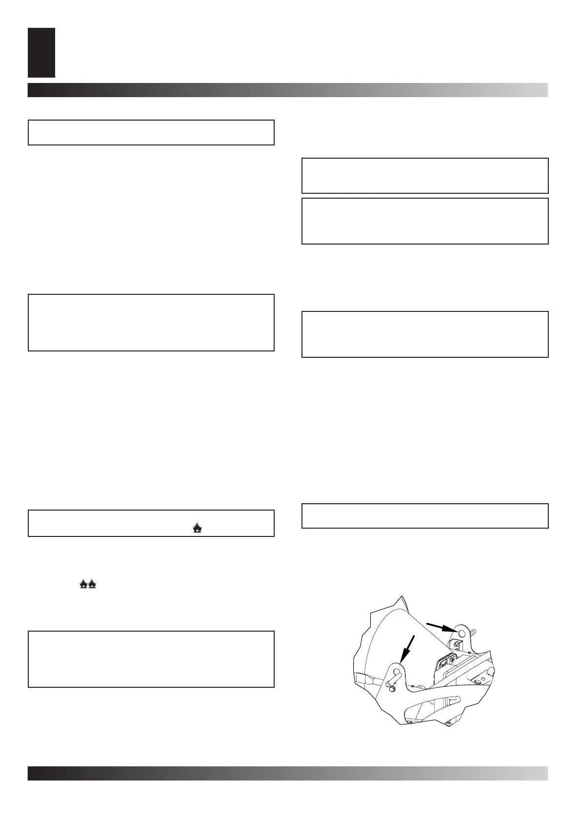
The generator is easy to move and it may be xed in a raised
position thanks to its special eye-bolt mechanism (B Fig. 3 or
Fig. 7). This enables it to be set in the most suitable position for
heating, defrosting and drying.
Figur 7 - Hooks in order to raise
 Loading...