6
en
C.
H.
D.
4 mm
4 mm
6-7 mm
E.
F.
G.
22 mm
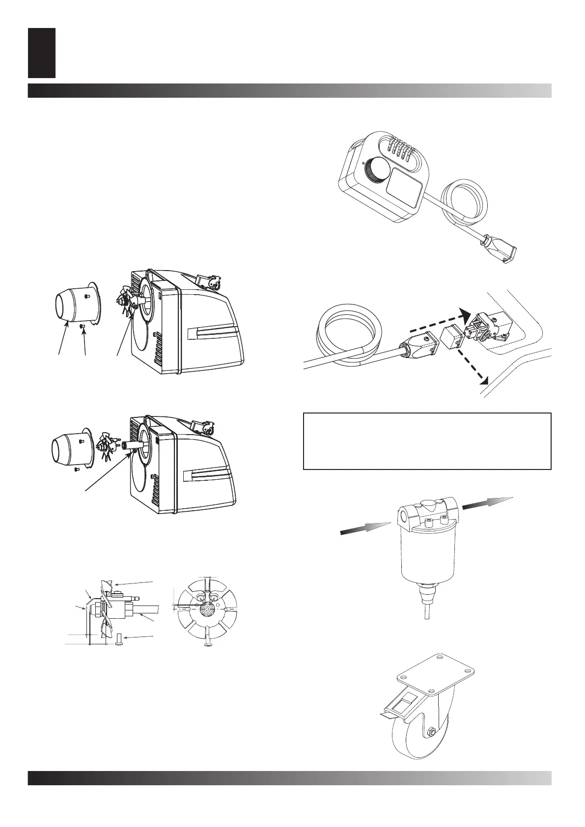
Figur 13 - Disassembly group diskame-electrodes
Figur 14 - Distances electrodes nozzle
A. Burner tube, B. Screw of the burner tube, C. Screw of the
group diskame-electrodes, D. Flame disk, E. Electrodes, F.
Tube, G. Nozzle, H. Screw
ROTATING WHEEL WITH BRAKES
PRE-HEATING FILTER
WARNING: Before beginning any maintenance operation
you must: stop the machine according to the instructions
provided in the paragraph “TURNING OFF THE GENERA-
TOR”; disinsert the electrical supply by unplugging it and
waiting for the generator to cool down.
A.
C.
B.
Figur 12 - Disassembly shell-burner
CONNECTING THE CONTROL DEVICE
ACCESSORIES
THERMOSTAT
CLEANING THE BURNER
• Remove the screw (H Fig. 5) that blocks the burner (A Fig. 3)
in the combustion chamber.
• Extract the burner from the combustion chamber (Fig. 3).
• Remove the three screws (B Fig. 12) that hold the burner tube
(A Fig. 12).
• Dismantle the tube.
• Remove the screw (C Fig. 13) that holds the group diskame-
electrodes and pull out the nozzle holder (F Fig. 14).
• Clean the ame disk (D Fig. 14) and the electrodes (E Fig. 14).
• Unscrew the nozzle (G Fig. 14) from the nozzle holder (F Fig.
14) clean it and if necessary replace it.
• Mount the nozzle (G Fig. 14) in its holder.
• Remount the group diskame-electrodes placing it at a correct
distance as the illustration (Fig. 14) shows.