Installation Manual
Type:DRDN20/40 DIN rail Type Redundancy Module
DRDN20-12 INPUT:1:9-14VDC 20A OUTPUT:20A (max)
2:9-14 VDC 20A
DRDN20-24 INPUT:1:19-29VDC 20A OUTPUT:20A (max)
2:19-29VDC 20A
DRDN20-48 INPUT:1:36-60VDC 20A OUTPUT:20A (max)
2:36-60VDC 20A
DRDN40-12 INPUT:1:9-14VDC 40A OUTPUT:40A (max)
2:9-14 VDC 40A
DRDN40-24 INPUT:1:19-29VDC 40A OUTPUT:40A (max)
2:19-29VDC 40A
DRDN40-48 INPUT:1:36-60VDC 40A OUTPUT:40A (max)
2:36-60VDC 40A
Introduction
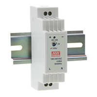
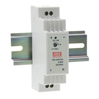
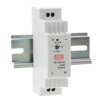
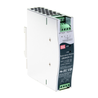
DRDN20/40 is a DIN rail type redundancy module.
Like other Mean Well’s DIN series, they can be mounted on a TS35 Standard DIN rail.
Installation
(1)Always allow good ventilation clearances, 5mm left and right, 40mm above and 20mm below, around the unit
in use to prevent it from overheating.
(2)The appropriate mounting orientation for the unit is vertical, the input terminals at the bottom. Mounting
orientations other than that, such as upside down, horizontal, or table-top mounting, is not allowed.
(3)Use copper wire only, and recommended wires are shown as below.
AWG 18 16 14 12 10 8 6
Rated Current of
Equipment (Amp)
7A 10A 15A 20A 30A 40A 50A
Cross-section of
Lead(mm
2
)
0.8 1.3 2.1 3.3 5.3 8.4 13.3
Note: 1. Current each wire carries should be de-rated to 80% of the current suggested above when
using 5 or more wires connected to the unit.
2. The maximum allowable wire cross-sectional area for the terminal is 6AWG/13.3 mm
2
Make sure that all strands of each stranded wire enter the terminal connection and the screw terminals are
securely fixed to prevent poor contact. If the power supply possesses multi-output terminals, please make
sure each contact is connected to wires to prevent too much current stress on a single contact.
(4)Use wires that can withstand temperatures of at least 80°C, such as UL1007.
(5)Recommended wire strapping length is 5mm (0.197”).
(6)Recommended screwdriver is 4mm, slotted type.