Do you have a question about the Mec 34-J Diesel and is the answer not in the manual?
Details the policies and responsibilities for safe operation and maintenance.
Explains safety symbols, colors, and essential safety practices for operation.
Provides detailed technical specifications for the machine's performance and dimensions.
Lists torque values for American standard cap screws based on grade and size.
Provides torque values for various hydraulic components based on SAE port size.
Outlines procedures for emergency stops and auxiliary power system usage.
Provides an overview of the hydraulic system's design and components.
Details fluid recommendations, handling precautions, and flushing procedures.
Describes the electrical control system, its modules, and operation.
Covers battery maintenance, charging, and replacement procedures.
Describes the functions and operation of the lower control panel.
Details components and layout of the upper control box, excluding PPSS.
Explains the process and importance of calibrating the GP500 control module.
Lists common failure messages and their solutions during calibration.
Covers routine maintenance procedures for the engine and its related components.
Identifies key lubrication points on the machine and recommended greasing intervals.
Offers general advice and common causes for system malfunctions.
Addresses common electrical system issues and diagnostic approaches.
Illustrates the electrical wiring for the lower control station and related components.
Depicts the hydraulic system's layout, components, and fluid flow paths.
Introduces the parts section of the manual and its usage.
Details components and layout of the upper control box, including PPSS.
Illustrates and lists parts for the jib assembly, part one.
Provides an exploded view and part list for the main boom assembly.
Illustrates and lists parts for the boom extend cylinder.
Details the main manifold valves, their descriptions, and quantities.
Shows the components and part numbers for the hydraulic tank assembly.
Illustrates and lists parts for the chassis assembly, part one.
Lists components for the cold weather option package.
Details the components for the 3.5kW generator option.
Lists parts for the 7.5kW generator manifold assembly.
Details components for the 7.5kW breaker box option.
Shows the location and identification of various decals on the machine.
| Brand | Mec |
|---|---|
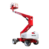
| Model | 34-J Diesel |
| Category | Lifting Systems |
| Language | English |