Page: 6/16
Warning: leave this mobile air-conditioner in an upright position for at least 2
hours before first use.
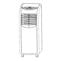
This air-conditioner may be moved indoor conveniently; leave the air-conditioner in an
upright position while moving it. The air-conditioner shall be placed on a flat ground surface.
Do not install or operate this air-conditioner in a bathroom or other wet environments.
1.1 .Installation of the C shape buckle of the heat exhaust hose and unit
Figure 1 Figure 2
1). Take out the C shape buckle of the heat exhaust hose and remove the plastic bag.
2). Point the rotary hole at the end of the heat exhaust hose snap toward the rotation shaft
of the back shell and slide it onto the back shell in accordance with the snap joint
direction of the rotation shaft on the back shell (as shown in Figure 1).
Note: 1. When the end snap joint at the end of the rotation shaft of the back shell sticks
out of the snap, it means that the heat exhaust hose snap has been slided into
place.
3).
Rotate the C shape buckle of the heat exhaust hose that is slided into place
counterclockwise to clip the snap joint of the C shape buckle of the back shell
successfully through the guide of the slide way of the back shell (as shown in Figure 2).
Note: 1. Do not rotate the C shape buckle of the heat exhaust hose if it is not slided into
place as this may damage the rotation shaft of the back shell and the C shape buckle of
the heat exhaust hose.
1.2 Installation of the heat exhaust hose assembly and unit
1). Pull the end of the heat exhaust hose apart by several turns;
2). Hold the end handle of the C shape buckle of the heat exhaust hose with the left hand
and the heat exhaust hose short connector with the right hand, put one end of the heat
exhaust hose that is pulled apart onto the snap of the lower air duct bottom, press the
C shape buckle of the heat exhaust hose with the left hand by force so that the C
shape buckle of the hea
t exhaust hose clips the snap joint of the back shell (as shown
in Figure 3).
Note: 1.The end of the heat exhaust hose must reach one step inside the bottom of the
lower air duct (as shown in Figure 4).
2.The few turns at the end of the heat exhaust hose must be snapped in the
snap of the lower air duct bottom.
Rotary hole
Rotation shaft of the
back shell
Slide way of the back
shell
Snap joint of the C
shape buckle of the