Quick Start Guide - MediaStar Evolution 785 HD Video Encoder
Installation
1. When locating the 785 Encoder, ensure that a clearance
distance of 25mm (1”) is maintained around the unit
to provide sufficient ventilation airflow. Items that could
accidentally block the ventilation grills or impede the cooling
airflow must not be located near the unit. The 785 must
not be installed where there is a possibility of exposure to
condensation, dripping or splashing liquids. Containers filled
with fluid should not be located in the vicinity of this unit.
Do not fix the Encoder to any surface which is a heat source
that may cause the unit to over-heat.
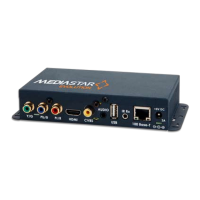
2. Connect the video source to the Encoder using the cables
supplied. If analogue audio is being used, connect the audio
source to the 3.5mm audio input socket.
3. Power on the encoder using the external mains-DC Power
supply or via the CAT5 network cable if using Power-over-
Ethernet (PoE).
When powering with the mains/DC power supply:
The external mains/DC power supply input rating must
meet the specifications of the mains supply at the installation
location. Only the LPS (Limited Power Source) power supply
provided with this equipment should be used. This device
must be installed using a mains (AC supply) plug and socket
that is located near the equipment, that remains operable
and be easily accessible to disconnect the unit in the case
of an emergency. Insert the DC jack plug of the mains/DC
power supply unit into the jack socket on the Encoder. Plug in
the mains/DC power supply unit, switch on and check that
the status indicator LED by the DC jack socket is lit.
When powering using PoE:
Connect the encoder to the network using the CAT5 cable
supplied or another equivalent cable of appropriate length.
The Encoder will then negotiate a class 3 power supply
connection with the PoE PS equipment. Check the status
LED by the DC jack socket is lit. If a mains/DC power supply
and PoE are used simultaneously, most power will be taken
from the DC supply and a small amount of power will be
taken from the PoE source so the link remains active.
4. The status LED (by the DC jack connector) will initially be
orange, then orange flashing as the encoder boots up.
When the LED goes green or flashing green, the encoder
is ready for use. The status LED shows the following states:
The LEDs on the network connector should illuminate to
indicate there is a valid network connection. The left-hand
green LED indicates a network link has been established,
and the right-hand orange LED is illuminated to indicate a
100Mbps connection. If the right-hand LED remains off, then
only a 10Mbps link has been established which may not be
adequate for successful video streaming.
5
. The encoder is supplied in the following default state:
IP Address: 191.53.51.208
Multicast Video/Audio stream: 239.192.11.12
Video acquisition: Search mode
Encoding: MPEG2, VBR, 10Mbps for SD input, 15Mbps
for HD input.
This means that as soon as a valid video signal is input on
to any one of the video inputs, a video/audio stream will
automatically be generated on multicast stream address
239.192.11.12. This stream can now be viewed using a
suitable software or hardware decoder.
If the Encoder does not see a valid video input, it will still
output a default plain colour picture.
6.
It is important to now change the IP address of the Encoder,
and its multicast output stream. If two encoders are on the
network at the same time and have the same IP address,
then accessing the browser based Encoder controls will
become impossible. If two encoders are on the network at
the same time and have the same video stream IP address,
then the picture on this stream will become un-watchable.
To change the IP address of the encoder, it is recommended
that you use the built in display and selection buttons.
However, you can also use an RS232, USB or IP serial link, or
connect to the Encoder via the network using a browser with
the Encoder’s default IP address.
Before setting the IP address of your encoder, contact your
network administrator to ensure any settings made are
appropriate for your network.
Built in Display Operation
The OLED display can be used with the three adjacent
push buttons to view status information and configure the
Encoder. The Up and Down buttons scroll up and down
the menus and change parameter values. The OK button
selects the currently displayed menu item or confirms a
parameter change. Pressing the Up and Down buttons and
releasing them together returns up a menu level, aborting
a parameter change in progress. Pressing the Up, Down
and OK buttons for 5 seconds and releasing them together
will present a unit RESET option. Pressing the OK button to
confirm will then reboot the encoder.
State LED
Reset Orange
Booting or stream disabled
(via browser page settings)
Flashing orange
Awaiting a valid video source Green flashing
Streaming video Green
Updating software Red flashing
Error Condition (service required) Red
 Loading...