Medlab medizinische Diagnosegeräte GmbH EG01010 User Manual
Version 1.06
4 5
Overview
The scope of this document is the description and specification of Medlab's three lead ECG board
EG01010. It should help anybody who is familiar with both programming and basic electronics to select
the proper hardware and software version for his application as well as to help him integrate the board
into his own electronic system.
The EG01010 measures one of three channels of ECG using a three lead cable. Through the use of the
second transmission protocol and an additional respiration board it is also possible to measure the respi-
ration rate.
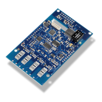
The ECG board has two connectors, as seen on the drawing on next page. The ECG module is
connected to the host system via the host and power connector. It provides the power supply for the
board and the communication with the host system. The EG01010 has full patient isolation on board, that
means that the input voltage of 5V has no galvanic contact to patient. The isolation gap can be easily
seen on the board and this area is only bridged by a transformer and the opto couplers. The patient cable
is connected to the ECG module by the patient cable connector. The ECG-board is defibrilation protected.
It is important that the board is directly connected to the ECG-cable connector and cable. This is to ensu-
re the patient isolation and the correct measurements of the board.
With a three lead cable, the module can output the following channels: I or II or III. Only one curve at a
time can be measured, e.g. Einthoven I or II or III. By using an optional respiration board in conjunction
with the second transmission protocol it is also possible to measure the respiration rate of the patient.
This is achieved by measuring the impedance change between the electrodes.
The isolated ground of the module is switched to the unused electrode in the respective setting, e.g. isola-
ted ground is on the left leg electrode if the module is set to channel I, left hand electrode if module is set
to channel II and right hand electrode if channel III is selected.
There are two transmission protocols for communication with the main unit available. The used protocol
is depending on the installed software version. The baud rate used for the data transmission is also
depending on the used protocol.