Medlab medizinische Diagnosegeräte GmbH EG01010 User Manual
Version 1.06
8
Header for patient cable connection
SV1: 1 Unused
2 SHIELD
3 LL-IN
4 RA-IN
5 LA-IN
6 SHIELD
7 Unused
Connectors
(see attached drawing for location)
Header for host connection
JP1: 1 Ground
2 Ground
3 Txd (RS232 level +/- 5Volt)
4 Txd (TTL level)
5 Rxd (RS232 level +/- 5Volt)
6 Rxd (TTL level)
7 Not connected
8 Not connected
9 Not connected
10 Not connected
11 Pulse Trigger output
12 Pulse Trigger output
13 Shutdown (V
CC
level on this pin powers down module)
14 Shutdown (V
CC
level on this pin powers down module)
15 V
CC
input
16 V
CC
input
Note: The pulse trigger is a high active, rectangular signal with a pulse width of 33 ms. Delay to the R wave can be
adjusted by a command.
and aVL and aVR and aVF and C
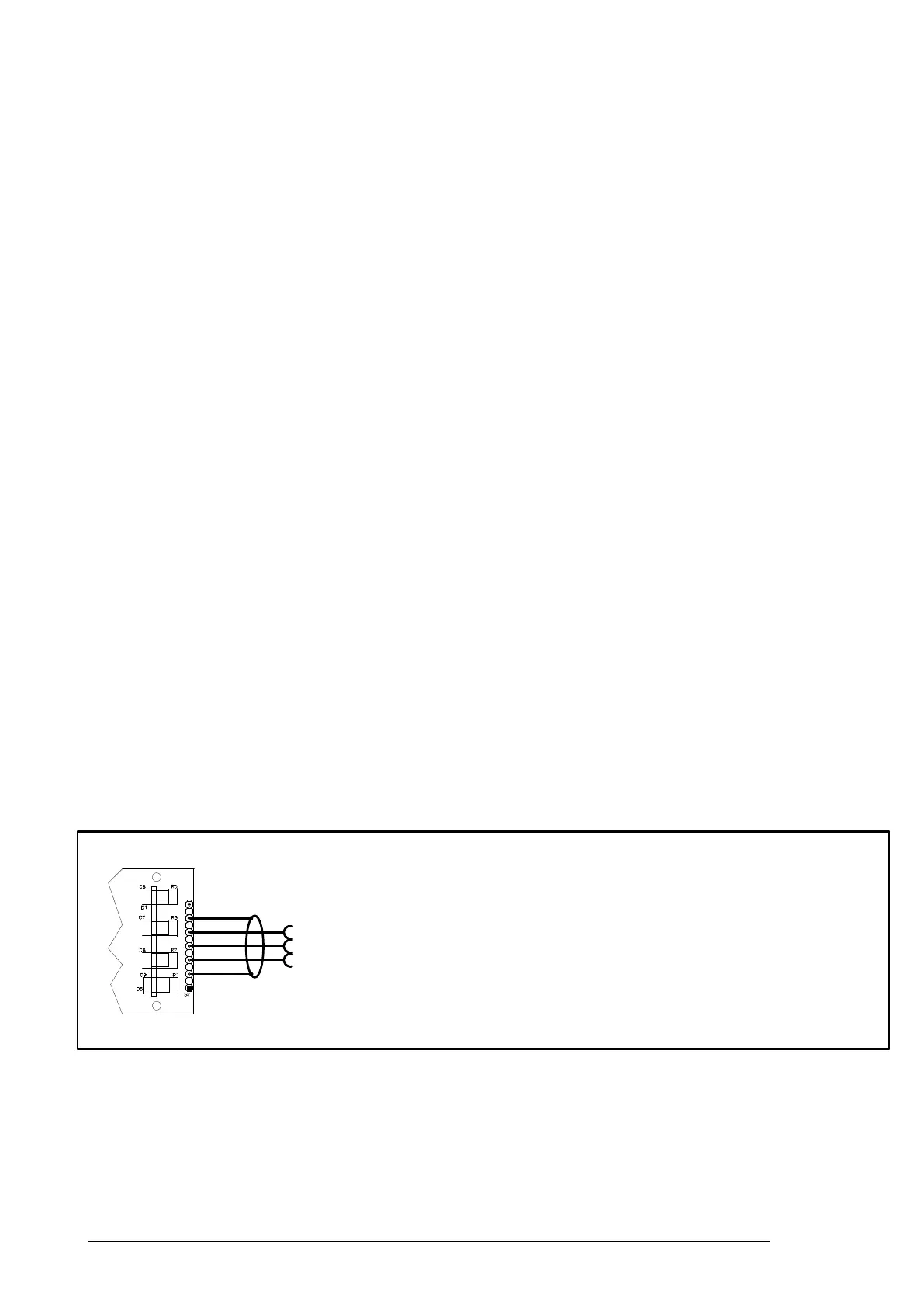
ECG cable connection
Remark:
For respiration measurement (optional respiration board needed), electrodes should
be attached to chest and hip, not arm and leg.
Please note that the leg clamp has to be connected to
the left leg or hip. If you connect this clamp to the right
leg or hip the signal quality decreases heavily.