EN
33
HOW TO USE
INTENDED USE
• This drill driver is intended for drilling and
screwing/unscrewing screws in wood and
metal.
• This drill driver is only intended for private
home use, not for commercial use.
• The drill driver must not be modied or
used for any other purposes than the ones
described in these instructions.
BATTERY
NOTE:
• Make sure the power switch is not
pressed in when inserting or replacing
the battery.
• Connect the battery with moderate
pressure – do not force. An incorrectly
connected battery can damage the
battery terminals or the battery socket
on the tool.
• To check the battery charge level, press
the "Press" button to see 1-4 red LEDs,
where 1 indicates low battery level.
FIG. 2
CHARGING THE BATTERY
• The battery must be charged before the
tool can be used.
• After charging for the rst time, use the
tool until the battery is completely
discharged. Repeat this charging and
discharging cycle 4 to 5 times.
• If the LEDs on the charger do not go on
when charging:
– check that the charger’s mains
adapter is properly plugged into the
power point and that the charger is
switched on
– check that the battery is correctly
inserted in the charger
Sound pressure level 79.0 dB(A), K= 5 dB
Sound power level 90 dB(A), K= 5 dB
Vibration level ¹ a
h,D = 1.3 m/s², K = 1.5 m/s²
Vibration level ² a
h,ID = 7.0 m/s², K = 1.5 m/s²
¹ Drilling in metal, ² Percussion drilling
Always wear ear protection.
The declared values for vibration and noise, which
have been measured according to a standardised
test method, can be used to compare dierent
tools with each other and for a preliminary
assessment of exposure. The measurement
values have been determined in accordance
with EN62841-2-1:2018.
WARNING!
The actual vibration and noise level when
using tools may dier from the specied
maximum value, depending on how the
tool is used and the material. It is therefore
necessary to determine which safety
precautions are required to protect the user,
based on an estimate of exposure in actual
operating conditions (taking into account all
stages of the work cycle, e.g. the time when
the tool is switched o and when it is idling,
in addition to the start-up time).
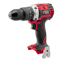
DESCRIPTION
1. Chuck
2. Torque setting ring
3. Function selector ring
4. Speed control
5. Rotation switch
6. Power switch
7. Handle
8. Battery
FIG. 1