48
TECHNICAL DATA
Engine type Air cooled, two-stroke
Displacement 25,4 cm³
Output 900W
Idling speed 3000 ± 300/min
Max speed 9000 rpm
Spark plug L8RTC
Volume fuel tank 500 ml
Fuel, mixing ratio 40:1
Axle diameter Ø 24 mm
Working width 380 mm
Trimmer line Ø 2 mm
Weight 4.9 kg
Sound pressure level, LpA 94.5 dB(A)
Sound power level, LwA* 105.8 dB(A), K=3 dB
Sound power level, LwA** 108 dB(A)
Max vibration level F: 5.43 m/s², K=1.5 m/s²
R: 4.79 m/s², K=1.5 m/s²
*Measured, **Guaranteed
F: Front handle, R: Back handle
Always wear ear protection.
The declared values for vibration and noise,
which have been measured according to a
standardised test method, can be used to
compare dierent tools with each other and
for a preliminary assessment of exposure. The
measurement values have been determined in
accordance with ENISO 11806-1:2011.
WARNING!
The actual vibration level when using power
tools may dier from the specied maximum
value, depending on how the tool is used. It is
therefore necessary to determine which safety
precautions are required to protect the user,
based on an estimate of exposure in actual
operating conditions (taking into account all
stages of the work cycle, e.g. the time when
the tool is switched o and when it is idling, in
addition to the start-up time).
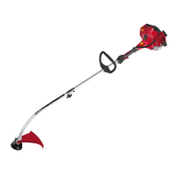
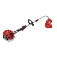
DESCRIPTION
1. Shaft coupling
2. Trimmer head
3. Guard
4. Shaft
5. Front handle
6. Back handle
7. Back cover
8. Fuel tank
9. Starter
10. Fuel cap
11. Choke lever
12. Air lter cover
13. Front cover
FIG. 1
ASSEMBLY
Fitting the shaft
1. Press in the bottom part of the shaft (b) as
far as it will go, so that the lock pin (a) goes
in the hole (c) in the shaft. If necessary turn
the bottom part of the shaft (b) back and
forth to make it easier. Check that the lock
pin (a) has gone completely into the hole.
2. Firmly tighten the locking screw (d).
FIG. 2
Fitting the handle
Put the rubber cap (3) on the shaft between the
two arrows. Fit the top part of the handle (2)