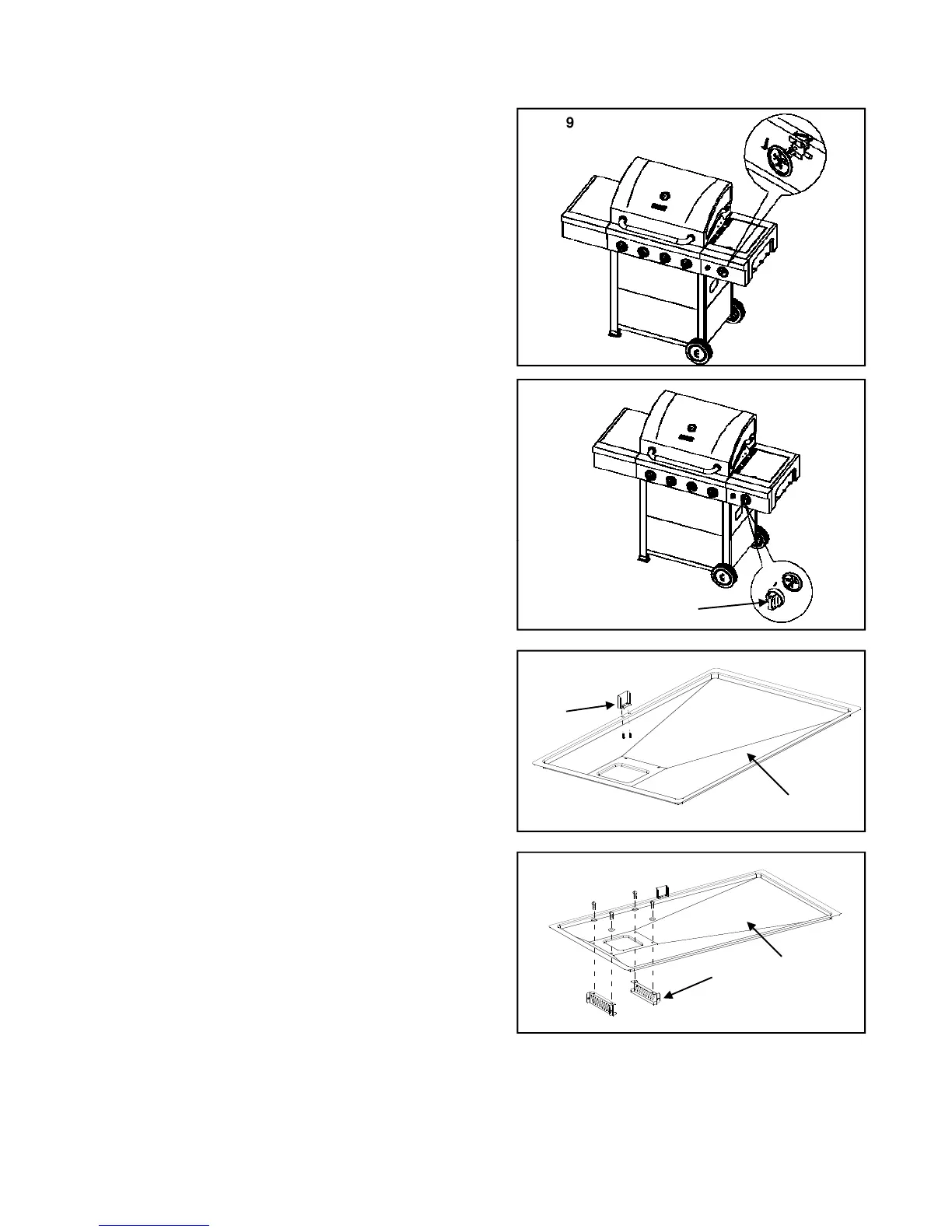
Fig. 19c) Loosen the screws which pre-assembled on the
side burner gas valve then align the screws to the valve
with the large side of the holes on the bezel, fix with
vertical gourd holes, then tighten the screws. As shown
in Fig. 19.
d) Insert Side Burner Control Knob (AA) into the valve
stem and tighten it. As shown in Fig.20.
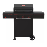
13. Grease Tray and Grease Box Installation
a) Attached Grease Tray Latch (AE) to Grease Tray (L) by
Tr ss Head Scre (H1) As sho n in Fig 21
.
L
AE
b) Attached Grease Cup Support Bracket B (V) to Grease
Tray (L) by using 4pcs Truss Head Screw (H1) and
4pcs Flat Washers (H4). As shown in Fig.22.
Fig. 22
V
L
4xH1
4xH4
20