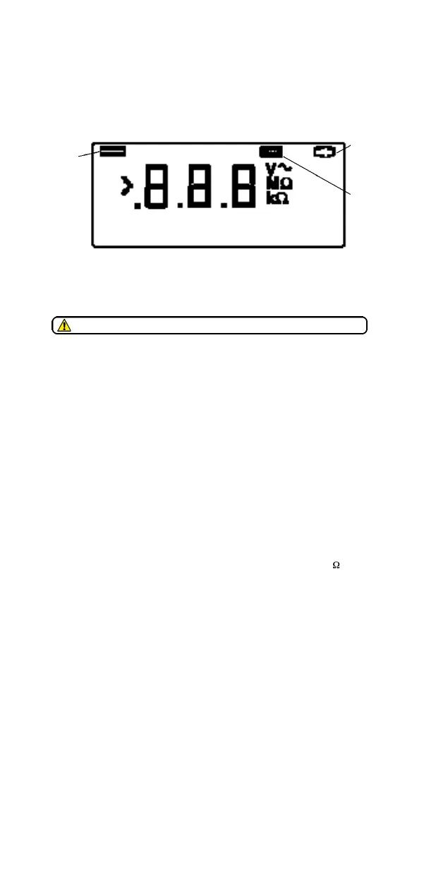
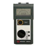
DISPLAY FEATURES
OPERATION
When briefly pressed and released, the instrument’s single control button
switches the instrument ‘O n’and selects C o n t i n u i t y mode. The Continuity test
automatically activates when the test leads make contact. Pressing and holding
the button selects I n s u l a t i o n m o d e .
Preliminary Test lead check
1. Before each use of the instrument, visually inspect the test leads to
confirm that their condition is good, with no damaged or broken
insulation.
2. Check continuity of the test leads by firmly shorting the leads together
and read the test lead resistance measurement directly from the
display.
Continuity Te s t i n g
1 Turn the instrument ‘ O n ’ by briefly pressing and releasing the test button.
2 Firmly connect the test leads together and note their combined
resistance value.
3 . Connect the test leads across the circuit under test.
4 . Take the reading directly from the displayed Continuity
r a n g e . ( M a x . 9 9 , 9 Ω ) .
5 . Subtract the test lead resistance value from the measured reading.
Insulation Te s t i n g
1 . Turn the instrument ‘ O n ’ by briefly pressing and releasing the test button
2 . Firmly connect the test leads to the isolated item / circuit under test.
3 . Press and hold the test button; the display changes to the M r a n g e
and shows the insulation value. As an additional safety feature the
BM122 display flashes its ‘ 1 0 0 0 V ’ symbol before performing the test.
4 . Release the test button beforeremoving the test leads (to enable the
instrument to discharge the circuit under test).
SPECIFICATION
I N S U L ATION B M 1 2 1 B M 1 2 2
Nominal Test Vo l t a g e : 500V dc 1000V dc
Test Voltage Accuracy: -0% +30% (0°C to 30°C) into 0 to 1mAload
Measuring Range: 0,01MΩ - 999MΩ
Short Cct. Current: Less than 2mA
Accuracy (at 20°C): ± 3% ±2 digits up to 10MΩ
± 5% ±2 digits up to 100MΩ
± 30% up to 999MΩ
CONTINUITY
Measuring Range: 0,01Ω - 99,9Ω
Open Cct. Voltage: 5V ±1V
Low
Battery
1000V
Fuse
Ruptured
Refer to Safety Warnings before using the instrument