AVTM651070 Rev B Nov 2006
9
4
Transmitter Operation
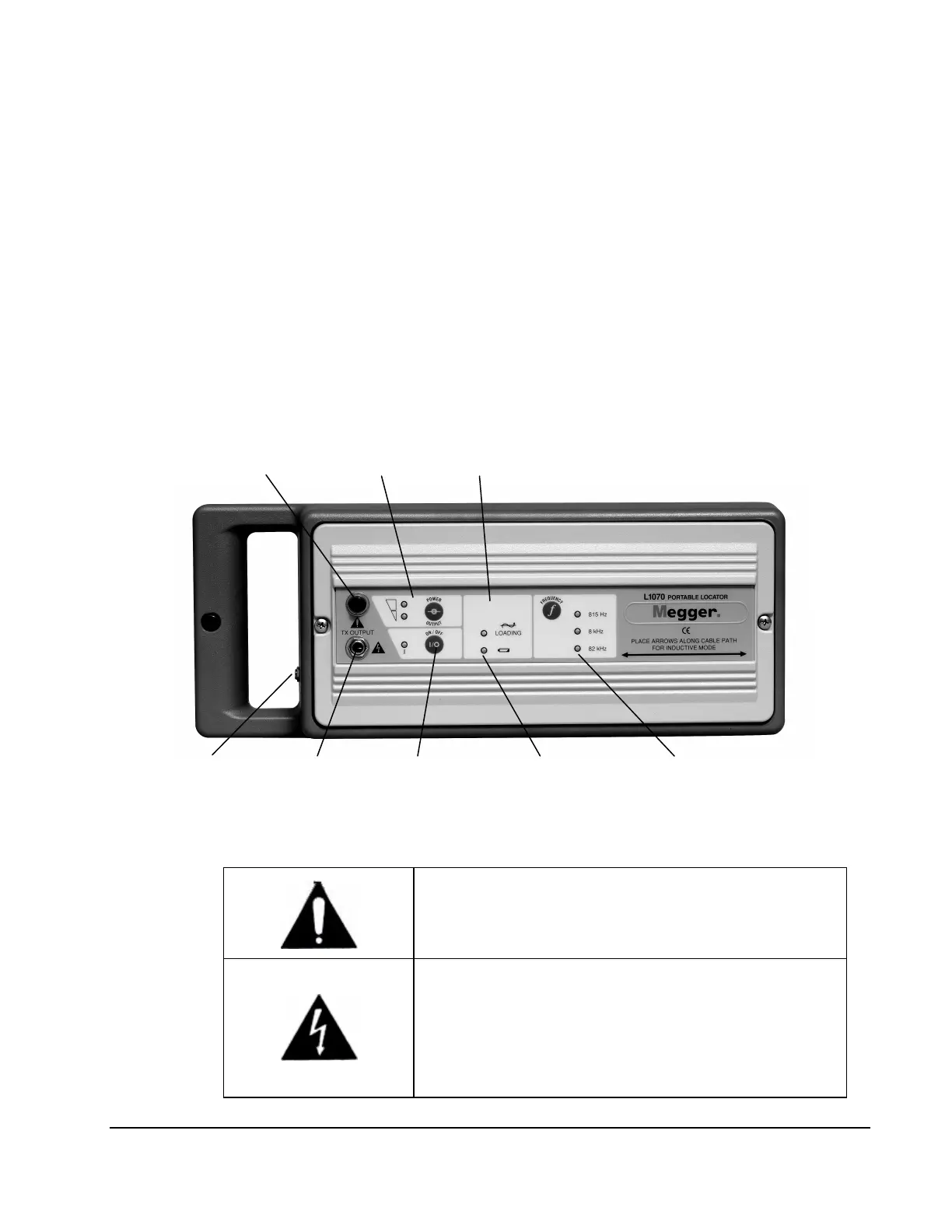
Controls and Indicators (Fig. 1)
Follow all safety precautions in Section 2 of this manual.
Figure 1: Transmitter Controls and Indicators
OUTPUT CIRCUIT BREAKER
The circuit breaker is tripped if the TRANSMITTER is
subjected to a voltage of 250V or 1.5 amps.
TX OUTPUT (SIGNAL OUTPUT JACK)
The TX OUTPUT is the jack. The RED/BLACK CORD and
the FLEXICOUPLER connects to create a circuit on the
buried utility.
WARNING: LETHAL VOLTAGE MAY BE PRESENT
CIRCUIT
CIRCUIT
IMPEDANCE
SIGNAL
JACK
OUTPUT
JACK
ON INDICATOR
REPLACEMENT
OR CHARGING
FREQUENCY
CONTROL


 To Next Page