AVTM651070 Rev B Nov 2006
21
5
Receiver Operation
Controls and Indicators
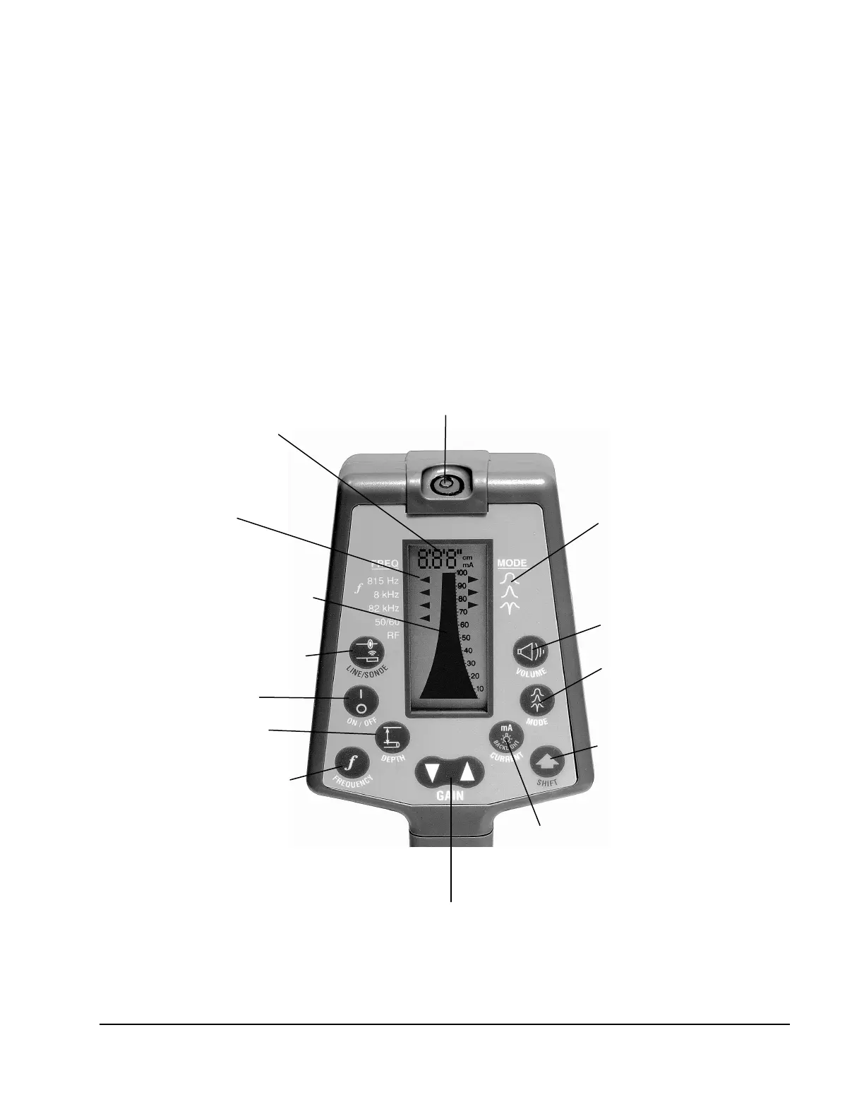
Figure 12 shows the controls and indicators on the receiver.
Figure 12: Receiver Controls and Indicators
SIGNAL STRENGTH,
DEPTH AND FAULT
IINDICATOR
BAR GRAPH
(single bar shows gain setting)
SONDE DEPTH MODES
MEASURES DEPTH
(with SHIFT key selects
either English or metric depth
measurement)
(for 45 degree depth)
Note: Hidden function.
Using SHIFT, select PINPOINT or
NORMAL PEAKING MODE
OR SETS OPTIMUM GAIN WHEN
SIGNAL IS OFF BARGRAPH SCALE
INDICATOR
NEED TO BE REPLACED
(Off, Low, Medium or High)
BUTTONS TO SELECT
ADVANCED FEATURES
SIGNAL FLOW IN CONDUCTOR
(Using SHIFT key for turning on
and off BACKLIGHT)


 To Next Page