14
display shows the last measurement made until the timer or voltage test
settings are changed or the test start/stop button is pressed.
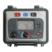
Analogue display
This simulates an analogue meter movement to give the user a better
“feel” for how a measurement is progressing. The analogue display
shows resistance only.
The display is also used to indicate how ‘result download’ and ‘deletion
of results’ is progressing.
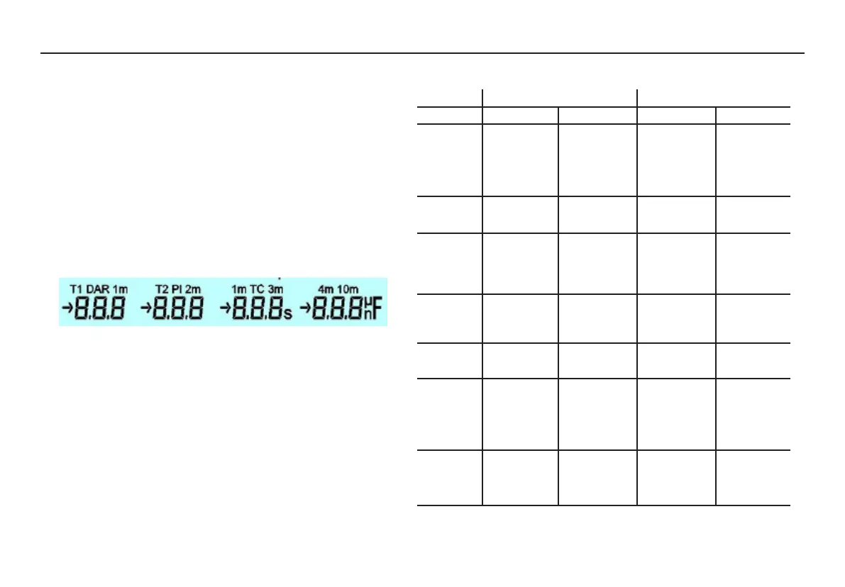
Secondary display
This part of the display shows the results of ‘time resistance’ method
tests.
‘Pre-Test / During test’ Key action table.
Button press Key action Fn + Key action
Pre-test During test Pre-test During test
Vs/Vt Increase / Increase / Increase / Increase /
decrease the decrease the decrease the decrease the
test voltage in test voltage in test voltage in test voltage in
major steps major steps minor steps minor steps
(IR only) (IR only)
Vs AND Vt Sets voltage Show set
to 500V voltage
Ts/ Tt Increase / Display set time Select main Display time
decrease the on main timer timer T1 or T2 set for main
time of the briefly timer, T1 or
selected timer T2 briefly
Ts AND Tt Reset timer to Display set Reset selected Display set
zero time on main timer to zero time on main
timer briefly timer briefly
Mode Select Test Cycle through
Mode IR modes
Ω/I Cycle through Cycle through
results display results display
of last test of current
completed active test
Record Turn recording Select
On/Off download or
clear stored
data
Vs and Vt represent the test voltage buttons. Ts and Tt represent the
timer buttons.
 Loading...