capacitance, time constant, voltage, timer measurements, and figure of
merit measurements such as polarisation index.
Features
n Continuous resistance or current measurement on main display.
n Optional resistance, current, or figure of merit measurements on
secondary display.
n Standard test voltages – 250 V, 500 V, 1 kV, 2.5 kV, 5 kV
n Non-standard test voltages – selectable between 50 V and 1 kV in 10 V
steps, and selectable between 1 kV and 5 kV in 25 V steps.
n Test modes include insulation resistance, polarisation index, step
voltage and dielectric discharge.
n 4 mA rms hardware noise current filter (selectable)
n Firmware filter 10, 30, and 100 seconds (optional)
n The dielectric absorption ratio is automatically calculated if the
corresponding timers are set.
n Either burn or breakdown selectable in insulation resistance mode.
n Insulation ‘Alarm Limit’ available in insulation resistance mode.
n Programmable timers include a main test duration timer, plus T1 and
T2 timers for time resistance method type tests.
n Load capacitance and time constant measurements – displayed at end
of test.
n LCD backlight.
n Data storage, data retrieval and real time data output.
n USB or RS232 communications.
n Battery level / charge level indicator.
INTRODUCTION
4
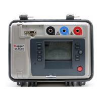
General Description
The S1-554/2 is a microprocessor controlled 5 kV insulation tester offering
measurement capability of up to 15 TΩ. The instrument performs
automatic tests and has data storage and data retrieval facilities.
Polarization index and dielectric discharge tests are performed
automatically, and test duration and voltages can be adjusted according to
user preference for these tests. A step voltage test can be performed
automatically, with a default voltage of 1 kV, and test duration of 5 minutes.
It is possible for the user to set different voltages and test durations for the
step voltage test.
The S1-554/2 incorporates a hardware filter designed to tolerate at least
4 mA rms of noise current at 50Hz and above. This filter is enabled by
default, but may be switched off in order to speed up the settling time
when there is little noise current. The Insulation Resistance mode offers
additional firmware filtering to average out slow variations during testing.
The S1-554/2 can be powered from the mains supply or by its own internal
rechargeable battery, which provides for at least 6 hours of continuous
testing with a 100 M
Ω load. A battery level indicator on the LCD display
indicates battery capacity. Connecting power to the mains supply
connector will automatically charge the battery whether the instrument is
switched ‘on’ or ‘off’, except during testing. A high level of internal
isolation allows the instrument to be used while the unit is supplied from
the mains. An internal battery management system switches the
instrument off after ten minutes of inactivity. If the battery approaches a
very low state of charge the instrument turns itself off, and mains power
must be applied before the instrument can be used again. Recorded test
results and settings will not be lost when the instrument is switched off.
A comprehensive LCD display shows resistance, current, filter setting,
 Loading...