8
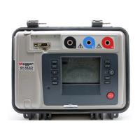
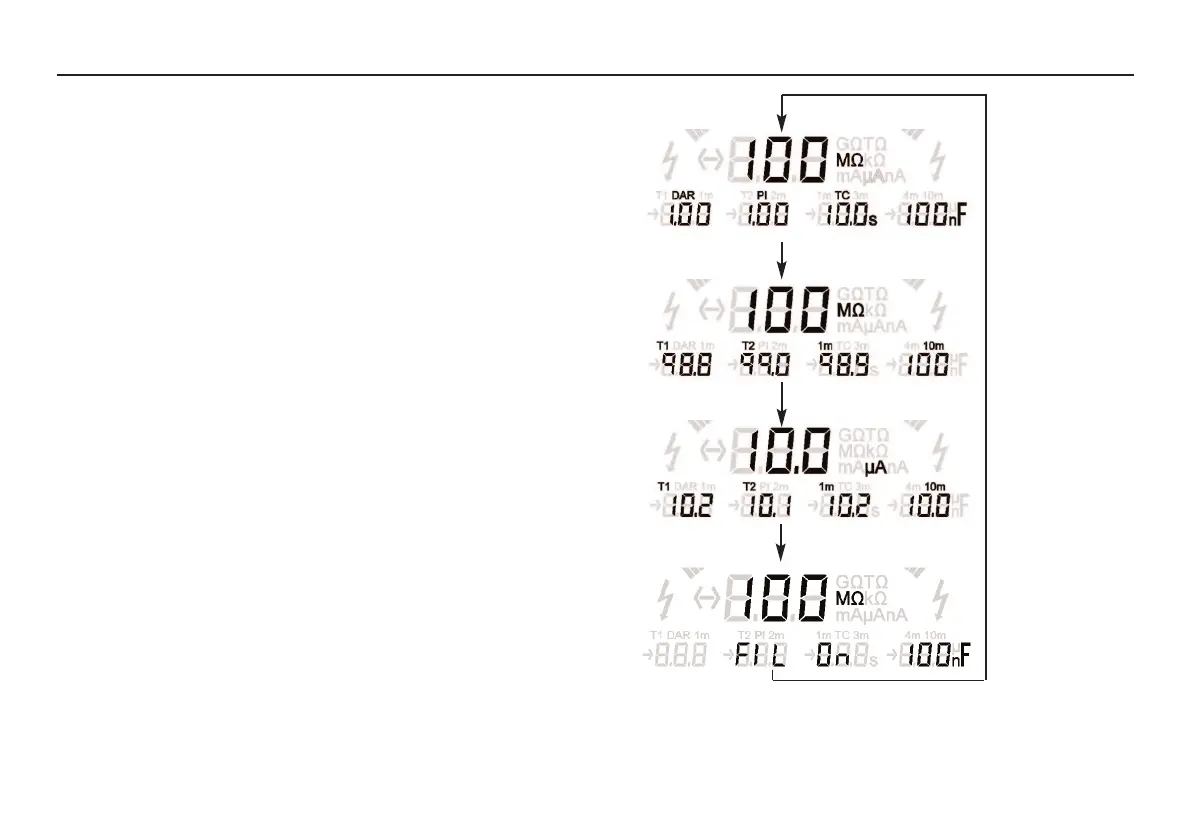
Figure 1 - The result of an insulation resistance test (IR)
Test settings: T1 and T2 times set in order to measure the DAR
Test conditions: test runs for longer than 10 minutes as this is required for
a PI reading.
of the test. The digital display toggles between insulation resistance and
current.
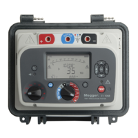
In the ‘IR’, ‘PI’, and ‘DD’ modes the secondary display initially shows the
PI (polarity index), DAR (dielectric absorption ratio), and, on completion
of the test, the TC (time constant) and capacitance measurements. Further
presses of the
Ω/I button cycles the display through insulation resistances,
currents, and the filter setting.
In the ‘SV’ (step voltage) mode, the secondary display cycles through
insulation resistances, currents, and the filter setting.
Figures 1 to 4 illustrate the display status for sequential ‘
Ω/I’ key presses in
the different modes.
Press
Ω/I
Press Ω/I
Press
Ω/I
Press Ω/I
 Loading...