M
AVTMTTR25 Rev C April 2008
42
T-Type Transformers
T-type transformers represent a special type of three-phase transformers. This
transformer may be tested as a single phase transformer.
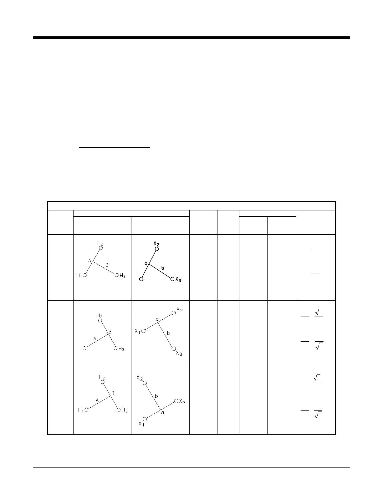
To make a measurement on a T-type transformer, the jumpers indicated in Table
C-1 should be applied to the appropriate terminals of the T-type transformer. The
TTR25 measured turns ratio should be compared to the calculated turns ratio
indicated in Table C-1.
Notes to Table C-1
1. Any connection(s) to ground/case of T-type transformer on H or X side should
be removed before testing a transformer.
2. Expect that polarity of the windings is normal (“+” sign is displayed in front of
the turns ratio test result)
Table C-1 ANSI Transformer Winding Phase Relationship
Winding Connection Winding Tested
IEC
Vector
Group
High-Voltage
Winding (H)
Low-Voltage
Winding (X)
External
Jumpers
Phase
tested
High-
Voltage
Winding
Low-
Voltage
Winding
Calculated
Turn Ratio
T-T
0
X
1
-
H
1
-H
2
X
1
-X
2
A
B
H
1
- H
2
H
1
– H
3
X
1
- X
2
X
1
– X
3
X
H
V
V
X
H
V
V
T-T
30
lag
H
1
H
2
-H
3
X
1
-X
2
A
B
H
1
– H
3
H
2
– H
3
X
1
- X
2
X
1
– X
3
2
3
•
X
H
V
V
3
2
•
X
H
V
V
T-T
30
lead
H
2
-H
3
X
1
–X
3
A
B
H
1
– H
3
H
2
– H
3
X
1
– X
3
X
2
– X
1
2
3
V
V
X
H
•
3
2
•
X
H
V
V