Do you have a question about the Meinberg IMS-M1000-S and is the answer not in the manual?
Manual contains installation/operation info and safety warnings. Follow regulations.
Device powered by dangerous voltage. Qualified personnel only. Observe standards.
Warning about electrical shock during wiring. Ensure proper installation.
Compliance with safety standards for antenna installation. Avoid lightning risk.
For skilled/service personnel only. Danger of explosion if replaced incorrectly. Dispose properly.
Connect system to equipotential grounding bus. Use correct grounding cable and crimp.
Illustrates an example setup for mounting the GPS antenna.
Optional surge voltage protector for coaxial lines. Connect shield to earth.
Message displayed on short-circuit. Disconnect power, eliminate defect, then repower.
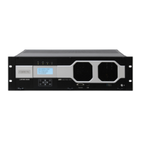
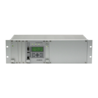
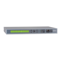
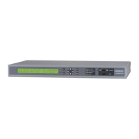
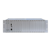
Housing, fuse, protection rating, power consumption, and physical dimensions.
Allows safe installation within temperature specs. Field-replaceable and hot-plug.
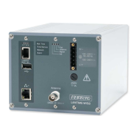
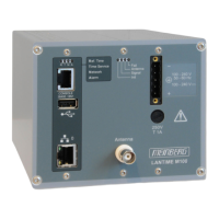
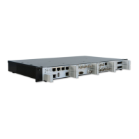
Lists modules, connectors, signals, and cable types for front/rear and module options.
Connect via RS232 D-Sub or RJ45. Use NULL-MODEM or CAB-CONSOLE cable.
USB interface for storage, updates, and configuration transfer.
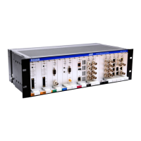
Overview of module types (ACM, I/O, CPU, CLK, ESI, MRI, PWR) for IMS slots.
Details slot configurations for standard and redundant M1000 versions.
Operational voltage, current, fuse, hotplug, and pin assignment for AC/DC PSU.
Operational voltage, current, power, fuse, hotplug, and pin assignment for DC PSU.
Details on GPS receiver, accuracy, antenna cable, connectors, and LED indicators.
Details on GNSS receiver, accuracy, cable length, connectors, power, and LED indicators.
DCF77 correlation receiver specs, sync time, outputs, accuracy, oscillator options, connectors.
Decodes and generates IRIG-A/B/G, AFNOR, C37.118, IEEE1344 time codes.
Controls switchover of reference clock in redundant systems. Manages outputs and interfaces.
Processor, memory, flash disk, network connector, and state LEDs for the LAN-CPU.
Enables synchronization to 1PPS, 10MHz, DCLS, and AM time codes. Has 4x BNC connectors.
Enhanced synchronization inputs for E1/T1 framed/unframed, variable frequencies.
Link speed, connectors, duplex modes, and LED indicators for LNE-GbE module.
IEEE 1588 v2 compatible profiles, PTP modes, NTP mode, and sync Ethernet capability.
IEEE 1588 v2 compatible TSU V3 specs, PTP modes, NTP mode, and LED indicators.
Configurable Port Expander / Backplane Port Expander for output signals.
Input signal, clock, BITS, outputs, short term stability, and LED indicators for LIU.
10MHz generator card with sine signals, microprocessor monitoring, and technical specifications.
Module to calculate and monitor frequency and deviation in power line networks.
Error relay output connected to TTL TIME_SYNC. Switches between NO/NC based on sync status.
Add-on module for generating audio frequencies and word clock rates. Provides four outputs.
Video signal reference for studio equipment. Generates video signals in different formats.
| Time Synchronization Protocols | NTP, PTP, SyncE |
|---|---|
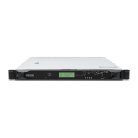
| Type | Time Server |
| GNSS Receiver | GPS, GLONASS, Galileo, BeiDou |
| Interfaces | USB, RS-232, RS-422, Ethernet |
| Network Interfaces | 10/100/1000Base-T, RJ-45 |
| Protocols | SNMP, HTTP, HTTPS, SSH |
| Oscillator | OCXO |
| Power Supply | 100-240 VAC, 50/60 Hz |
| Operating Temperature | 0°C to 50°C |
| Dimensions | 1U, 19" rack mountable |