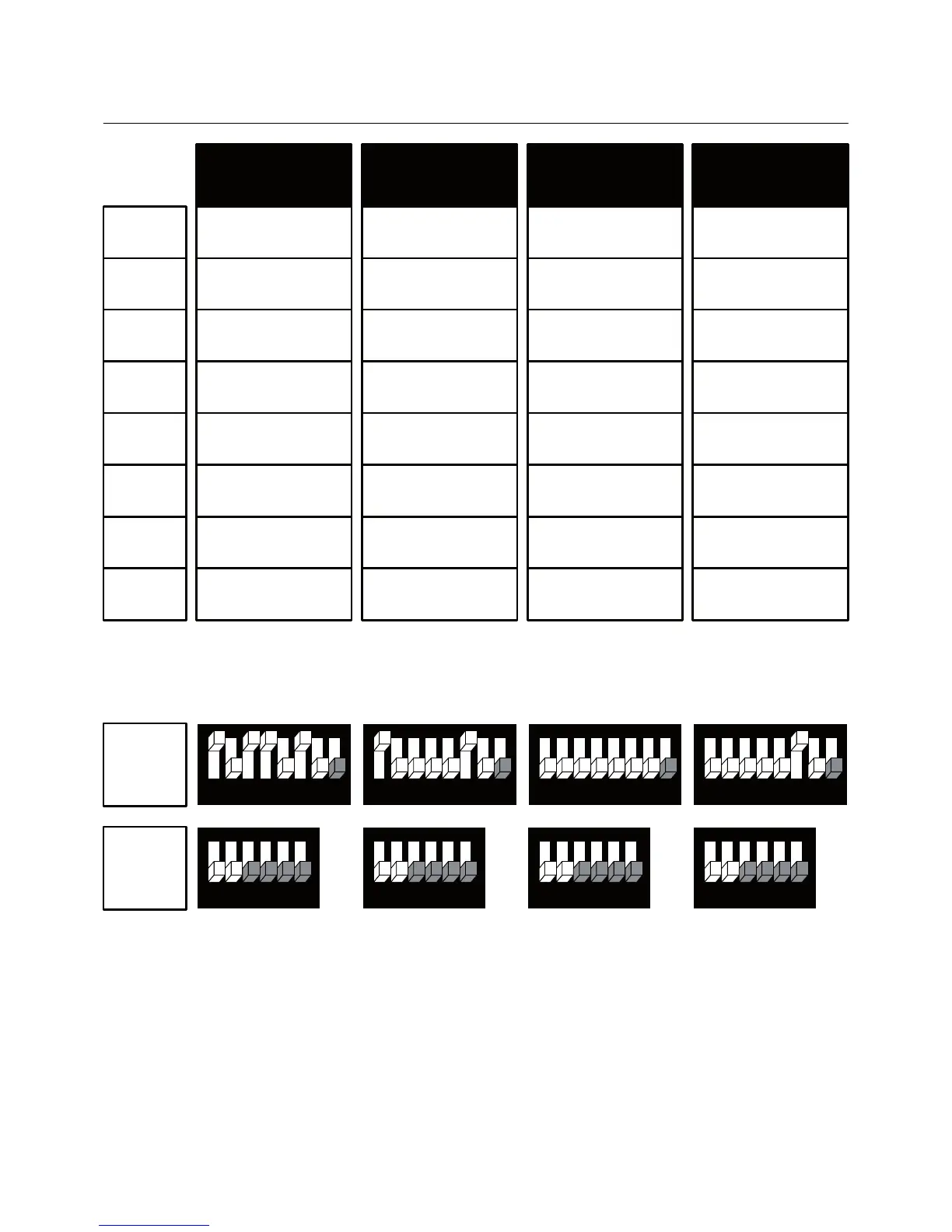
3. Wiring configuration and DIP Switches – AC systems
-14 -
HC32
1 Speed fan
11
12
13
14
15
16
AO1
AO2
Heat element 3
Heat element 2
Fan (1 speed)
Compressor 2
Compressor 1
Heat element 1
(see SW1.4 HC)
X
X
HP42
1 Speed fan
Heat element 1
Heat element 2
Fan (1 speed)
Compressor 2
Compressor 1
Heat pump
(see SW1.4 HP)
X
X
HP22
3 Speed fan
Fan medium
Fan high
Fan low
Compressor 2
Compressor 1
Heat pump
(see SW1.4 HP)
X
X
HP21
3 Speed fan
Fan medium
Fan high
Fan low
Heat element
Compressor 1
Heat pump
(see SW1.4 HP)
X
X
87654321
654321
SW1
SW2
87654321
654321
87654321
654321
87654321
654321
MTSC Series: SW1.8 = Communication Protocol: ON – BACnet, OFF – MODBUS
SW1.4 = HP: ON – Heat pump active in cool, OFF – Heat pump active in heat
HC: ON – Electrical heater, OFF – Oil/Gas heater (no fan)
SW1.5 = ON: Disable compressor delay, OFF – Enable compressor delay
S2.3 – S2.6 – Not in use
HP - Heat pump system HC - Non heat pump system ## - Heating/Cooling stages
Fan on/off: 24/110/230VAC, 3A max.
Control - Heat elements, Heat pump, Compressors: 24/110/230VAC, 0.3A max.