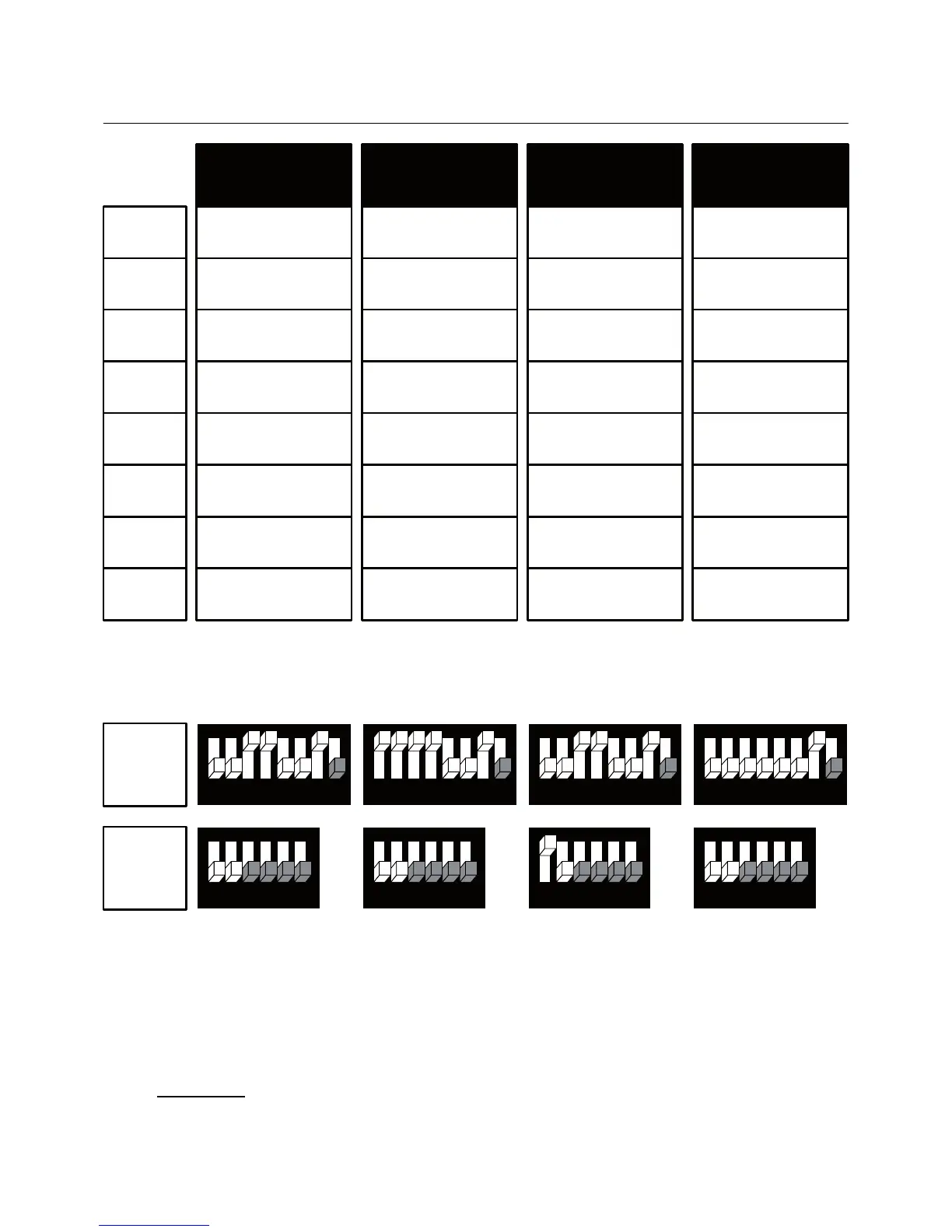
3. Wiring configuration and DIP Switches – Fan coil systems
-17 -
11
12
13
14
15
16
AO1
AO2
SW1
SW2
MTSC Series: SW1.8 = Communication Protocol: ON – BACnet, OFF – MODBUS
SW1.4 = Enable/Disable 2
nd
heating stage: ON – Enable, OFF – Disable
SW1.5 = Chilled beam option (fan will not run with 1
st
stage cooling) – SW1.5 ON
S2.3 – S2.6 – Not in use
**For Cool only
configuration, change technician parameter P9 to “01” (change
over sensor) and leave contact IN,0 open.
4-Pipe
3 Speed fan
Fan high
Fan medium
Fan low
Heat element
(2
nd
stage heat)
Cool valve
Heat valve
(1
st
stage heat)
X
X
4-Pipe, 3 Speed
Cool-PID
X
X
87654321
654321
87654321
654321
Fan high
Fan medium
Fan low
Cool valve PID
4-Pipe, 3 Speed
Fan VFS
Fan high
Fan medium
Fan low
Cool valve
X
Fan VFS
87654321
654321
Heat element
(2
nd
stage heat)
Heat valve
(1
st
stage heat)
Heat element
(2
nd
stage heat)
Heat valve
(1
st
stage heat)
Fan on/off: 21/110/230VAC, 3A max.
Fan VFS, PID valves: 0-10VDC. 5mA Not isolated
Control - Heat elements, Cool/Heat valves, Compressors: 24/110/230VAC, 0.3A max.
2-Pipe, 3 Speed
Cool only**
Fan high
Fan medium
Fan low
X
Cool valve
X
X
X
87654321
654321