7
WIRING FOR 485 AND 232 SERIAL COMMUNICATION OPTIONS
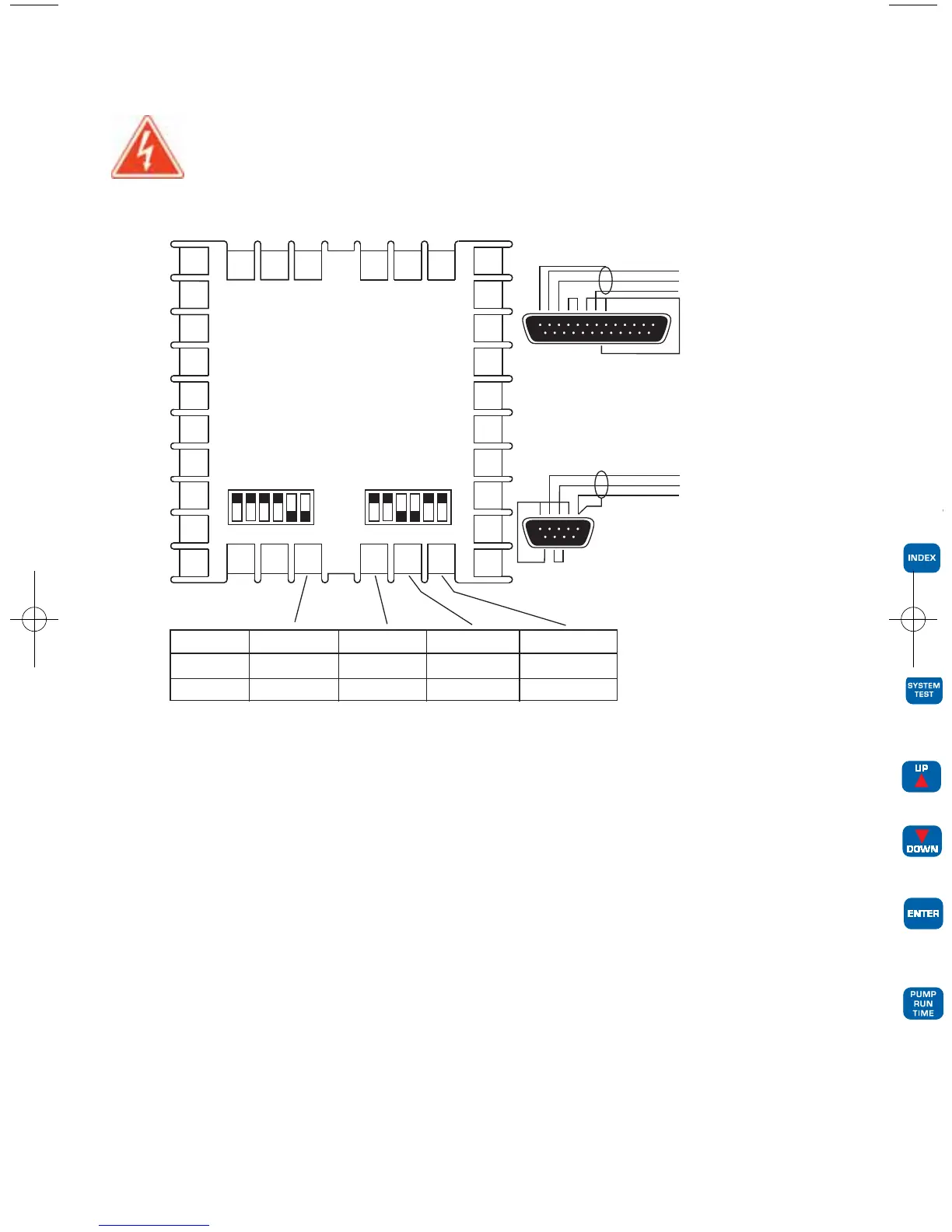
Wire power and outputs as shown on page 5. Wiring for options is shown in Figure 4 below.
All wiring shown below is Class 2. Shielded twisted pair is recommended for Option 485.
DO NOT run signal wiring in the same conduit or chase as the power wiring.
Erratic operation or damage to the control circuitry will result.
Figure 4 – Wiring for Options
10
9
8
7
27 28
29
30
31
32
20
19
18
17
6
5
4
3
2
1
21
22
23
24
25
26
16
15
14
13
12
11
Terminal 29 30 31 32
Option 485 Y (receive -) Z (receive +) A (transmit -)* B (transmit +)*
Option 232 not used data out data ground data in
*For half-duplex operation wire only A and B. Do not connect to Y and Z.
Option 485 DIP Switch Positions*
Half Duplex* Full Duplex
1 2 3 4 5 6
1 2 3 4 5 6
1 2 3 4 5 6 7 8 9 10 11 12 13
14 15 16 17 18 19 20 21 22 23 24 25
DATA IN 30
DATA OUT 32
DATA GROUND 31
PIN DESCRIPTION
1 SHIELD
2 TRANSMIT
3 RECEIVE
4 RTS
5 CTS
PIN DESCRIPTION
6 DSR
7 GROUND
8 DCD
20 DTR
DB-25 WIRING
(VIEWED FROM WIRE SIDE)
1 2 3 4 5
6 7 8 9
RS-232 DB-9 WIRING
(VIEWED FROM WIRE SIDE)
PIN DESCRIPTION
1 DCD
2 RECEIVE
3 TRANSMIT
4 DTR
5 GROUND
6 DSR
7 RTS
8 CTS
DATA OUT 32
DATA IN 30
DATA GROUND 31
ON
OFF
L-20:L-20 9/30/10 11:08 AM Page 7
 Loading...