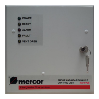
Smoke and Heat Exhaust Control Unit mcr 9705 – User Instruction Manual
Strona 12 z 24
Never change the default settings of the voltage potentiometer for the batteries.
In case of a system defect CALL THE SERVICE
3.8. Curtain control - Additional info
For mcr PROSMOKE CE / CE1 curtains use the mcr 9705 control unit with the
"curtain" option. Set the control unit into the curtain control mode (SW1-5 and SW1-6
ON).
For mcr PROSMOKE FSv2 CE curtains, use the standard mcr 9705 control
panel. The control panel should be set to door automation mode (SW1-6 ON).
The control unit’s standby time in cooperation with the curtains mcr PROSMOKE
FSv2 CE depends on the number of connected smoke curtains - additional
information in the DTR of mr PROSMOKE FSv2 CE smoke curtains.
4. Assembly and start up
1. Sensors line - 2 leads (e.g. YnTKSY) from P11 terminals. Terminal resistor 5,1
kΩ in the base of the last sensor. The maximum number of sensors is limited in
accordance with the list of technical parameters (see chapter 9 Technical
specifications).
2. Smoke exhaust pushbuttons line (RPO) - 7 leads from P9 (alarm closing
contact), P10 (control inputs) and P17 terminals (indicator output). Terminal
resistor 10 kΩ in the last pushbutton. The maximum number of pushbuttons in
accordance with the technical parameters (see page 20).
3. Actuators line - 2 leads in silicone insulation (feature PH30, for example HLGs),
from P8 terminals. Terminal resistor 10 kΩ in the last connection box. The line is
protected by a 6,3 A or 8 A fuse (FS3). The maximum number of actuators in
accordance with the technical parameters. Only specific leads shall be used,
leads that are compatible with actual regulations.
Attention: In case of multi module centrals – do not connect galvanized outputs
[to actuators] of different modules.
4. Ventilation - pushbuttons for ventilation (manual vent control- upwards,
downwards) – 3 leads (e.g. YTKSY or YDY) from P6 terminals. It is possible to
connect several pushbuttons in parallel.
5. Hatch function - switch with key (for switching between the functions
"ventilation" - "hatch") - 2 wires (YTKSY or YDY) from terminals P1
6. Automatic weather monitoring unit for closing the vents in case of a strong
wind/ heavy rain - 2 leads (e.g. YTKSY or YDY) from P7 terminals.
7. External alarm input to the 24 V relay coil – 2 leads (e.g. YnTKSY) from P13
terminals. If the device which activates the alarm (fire alarm control unit) has a
24 V output, it shall be connected directly to the P13 terminal. Loss of voltage at
the P13 terminal will activate the alarm. If the device which activates the alarm is
equipped with a voltage-free null contact (NC), we have to use the loop power
supply available on the P12 terminal (see Diag. 1 or Pic. 3). The P12 terminal is
short-circuit resistant and can carry a load of maximum two relays. Once the line
is connected remove the H1 jumper which blocks the external alarm.

 Loading...