Smoke and Heat Exhaust Control Unit mcr 9705 – User Instruction Manual
Strona 16 z 24
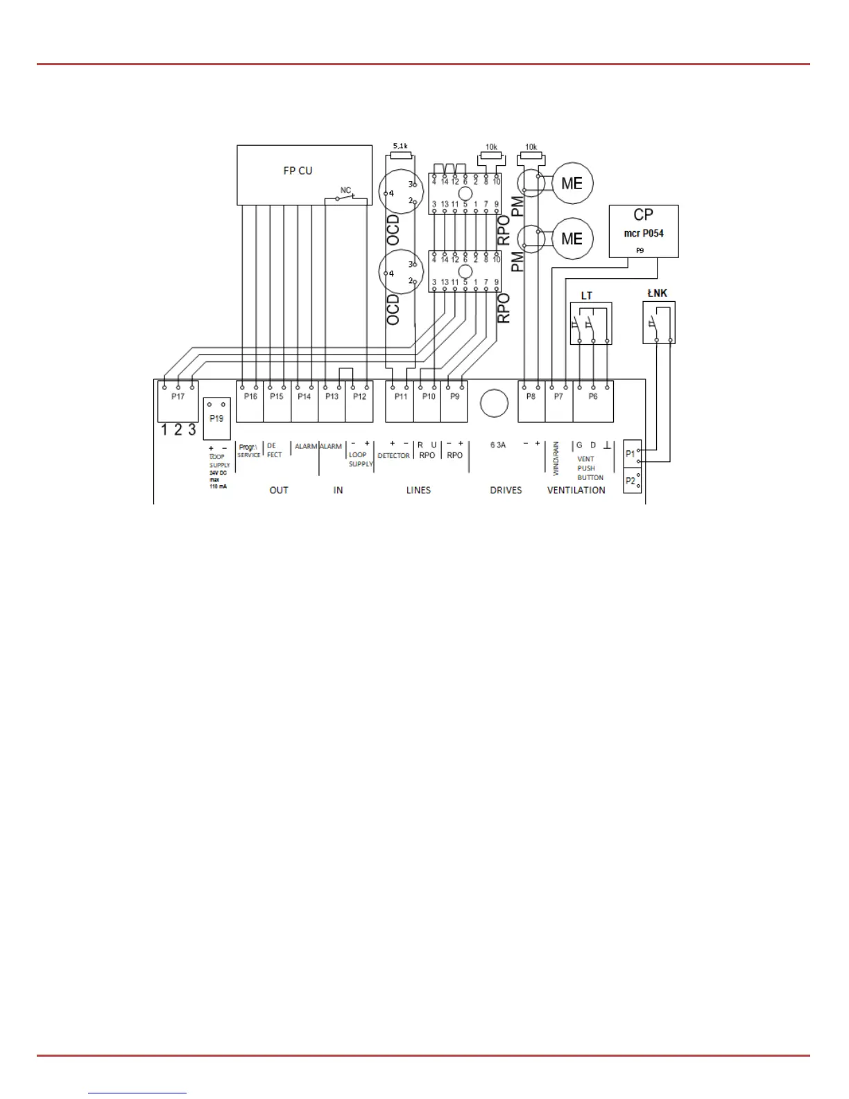
6. Typical connection diagrams
Diag. 1 Typical configuration of a smoke exhaust system equipped with the mcr 9705-5A
control unit.
Elements:
CP - weather monitoring unit mcr P054
LT - ventilation pushbutton
ŁNK - key switch for activating the "hatch" mode
ME - electromechanical actuator
OCD – optical smoke sensor (e.g. KL731)
PM - connection box
RPO – manual smoke exhaust pushbutton mcr RPO-1
Attention!
Not all the elements of the system (in particular the fire protection control unit and the
weather monitoring unit) must be present in the smoke exhaust system.