INSTALLATION
45
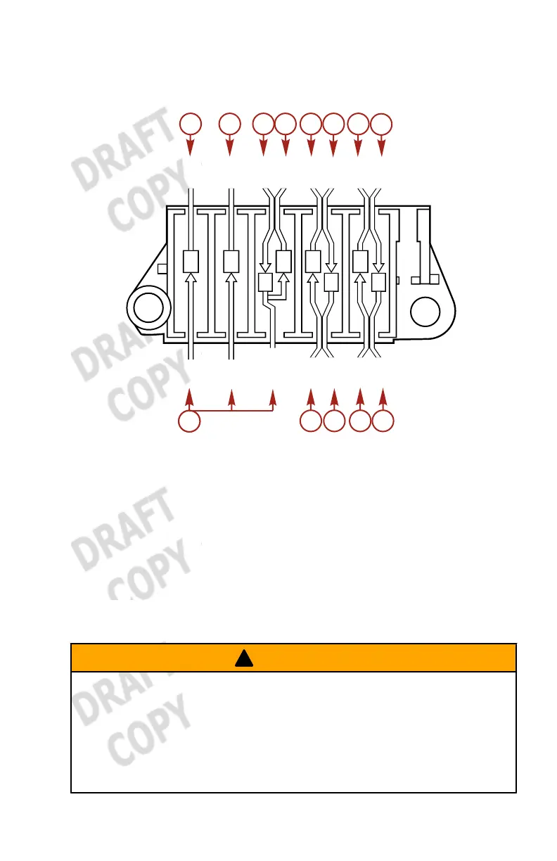
18.Connect the cables to their respective terminals at the cable
terminal holder.
YEL
WHT
RED
BRN
BLU
BLK
GRN
YEL
WHT
RED
BRN
BLU
BLK
GRN
RED
37500
a
b
c
d
e
f
g
h
i
j
k l
m
i
a - Magnet lead wire
b - Magnet lead wire
c - Cord assembly
d - Fuse wire
e - CD unit
f - Cord assembly
g - CD unit
h - Starter solenoid
i - Rectifier lead wire
j - Stop switch
k - Choke solenoid
l - Stop switch
m -Cord assembly
Attaching the Steering Link Rod
!
WARNING
Improper fasteners or improper installation procedures can result
in loosening or disengagement of the steering link rod. This can
cause a sudden, unexpected loss of boat control, resulting in
serious injury or death due to occupants being thrown within or
out of the boat. Always use required components and follow
instructions and torque procedures.

 Loading...