Section 5 - Storage
90-8M0113857 eng DECEMBER 2015 Page 75
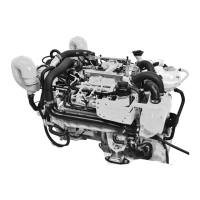
5. Pull the lever on the air pump (vertical) to lock the pump onto the fitting.
a - Actuator fitting
b - Green indicators
c - Manual release valve
d - Blue air pump
e - Lever (locking)
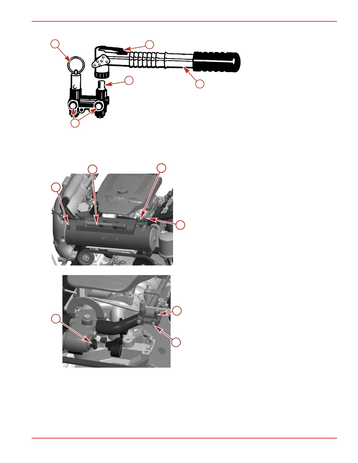
6. Pump air into the system until both green indicators extend and water drains from both sides of the engine. The port side
will begin draining before the starboard side.
7. Immediately remove the blue drain plug from the side of the thermostat housing or the heat exchanger. This must be
removed within 30 seconds to properly vent the cooling system.
Closed cooling models (V8 model shown)
a - Blue drain plug location
b - Blue air pump
c - Air manifold
d - Green indicators
Seawater cooled models
a - Blue drain plug location
b - Air manifold
c - Green indicators
8293
b
d
e
a
c
 Loading...