CYLINDER BLOCK AND CRANKCASE
90-857138R1 MAY 2000 Page 4B–35
CAUTION
Eye protection must be worn while installing piston rings.
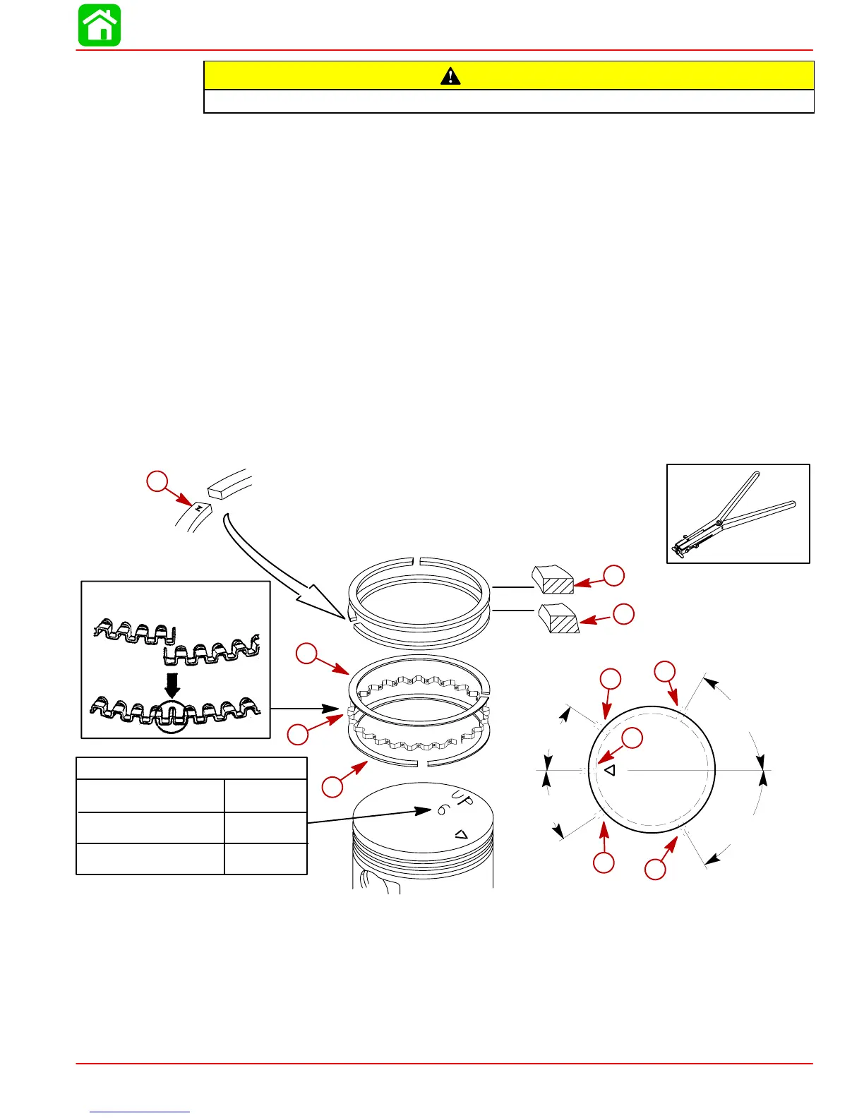
IMPORTANT: Do Not mistake the top and second piston rings. The rings are different
and must be installed in correct order.
NOTE: The piston ring end gaps must be staggered
as shown to avoid alignment with the
piston pin.
8. Install the oil ring as follows:
a. Set the oil ring expander in the oil ring groove. Position the ring ends with the 120°
location as shown. Match the ring ends correctly as shown in Figure1.
b. While holding down the oil ring ends by a thumb, install the upper side rail. Position
the end gap at 13/16 in. (20 mm) to the left of the oil ring ends.
c. As in the same manner as the above step b, install the lower side rail. Position the
end gap at 13/16 in. (20 mm) to the right of the oil ring ends.
9. Install the top and second ring in the correct order. Install the piston rings with the mark-
ing side facing up.
10. Make sure the rotation of the piston rings are smooth.
11. Position the piston end gaps at the positions shown.
Incorrect
Correct
91-24697
a
c
d
e
b
f
Figure 1
13/16 in.
(20 mm)
13/16 in.
(20 mm)
60°
60°
g
h
i
j
k
Piston ID
4/5 (1999 & 2000)
6 (2000)
4/5/6 (2001)
No Mark
6
6
a-Top Ring – Chrome
b-Second Ring – Tapered
c-Upper Side Rail
d-Oil Ring Expander
e-Lower Side Rail
f-Install Rings With Marking
Side Facing Up
g-End Gap – Top Ring
h-End Gap – Second Ring
i-End Gap – Upper Side Rail
j-End Gap – Oil Ring Expander
k-End Gap – Lower Side Rail
 Loading...