RIGHT HAND NON-RATCHETING
90-855347R1 JANUARY 1999 Page 6A-39
Propeller Shaft
REASSEMBLY/INSTALLATION
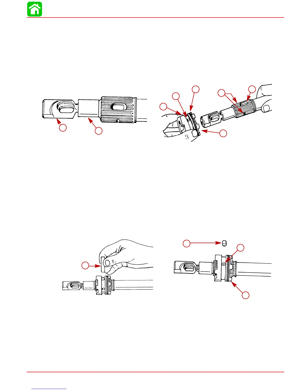
1. Insert clutch actuator rod assembly into end of propeller shaft. Align cross pin slot in
actuator rod with cross pin slot in propeller shaft.
2. On PRODUCTION MODEL GEAR CASES, position sliding clutch onto propeller shaft
with GROOVED RINGS (ON SLIDING CLUTCH) TOWARD PROPELLER END OF
PROPELLER SHAFT. Cross pin hole and detent holes (in sliding clutch) must line up
with cross pin slot and detent notches on propeller shaft.
51864
51864
c
d
e
f
g
h
a
b
a-Cam Follower
b-Propeller Shaft
c-Sliding Clutch
d-Grooved Rings
e-Cross Pin Hole
f-Detent Hole (Behind Finger and Thumb)
g-Detent Notch (One on Each Side)
h-Cross Pin Slot
3. Insert cross pin thru sliding clutch, propeller shaft and actuator rod, forcing cross pin
tool out.
4. Apply a small amount of 2-4-C w/Teflon Marine Lubricant on detent pin. Position a det-
ent pin in detent pin hole of sliding clutch with rounded end of pin toward propeller
shaft.
51864
51864
b
c
d
a
a-Cross Pin
b-Detent Pin
c-Cross Pin
d-Sliding Clutch
 Loading...


