3
DN
UP
P
S
6
6
1
2
3
7
A
B
C
B
D
2
3 4
5
8
1
DN
UP
1
2
3
P
S
1
A
B
C
B
D
8
2
3 4
5
6
6
7
DN
UP
P
S
6
6
1
2
3
7
Green Grey White Red
2
3 4
5
8
1
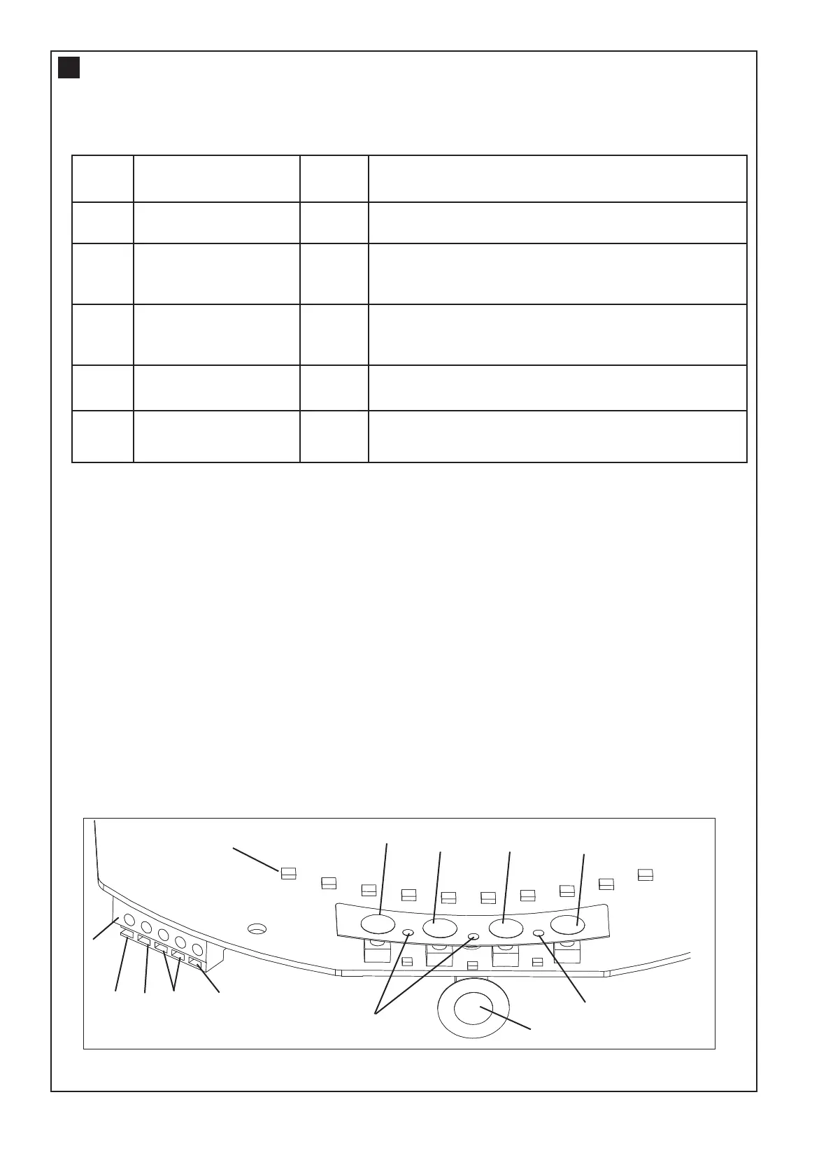
1
. Terminal Block: used for external accessories (see chart below).
NOTE: The terminal block is behind a plastic cover in the back housing. Use a small screwdriver to lever
open the plastic cover if access to the terminal block is required. All wires should be secured appropriately.
2. DN Button: used to drive the door DOWN.
3. UP Button: used to drive the door UP.
4. P Button: used to “PROGRAM” the DOOR LIMITS (see section 14).
5. S Button: used to “SAVE” and “DELETE” the “TRANSMITTERS” (see section 22).
6. LEDs: 1. Program DOWN, and Diagnostic code indicator Number 1.
2. Program UP indicator.
3. Diagnostic code indicator Number 2.
7. Control Button: Used to activate the door when transmitters are not available. Open - Stop - Close.
8. Courtesy Light: turns on during operation and automatically turns off after a period of 3 minutes .
Colour Function Polarity Comment
Red Push button +ve Dry contact input for push button wired wall
controls
White Common -ve Common terminal for push button, The Protector System
TM
(IR Beams) & accessory power
White Common -ve Common terminal for push button, The Protector
System
TM
(IR Beams) & accessory power
Grey The Protector System
TM
(IR Beams)
+ve The Protector System
TM
(IR Beams) input (pulsing
type only)
Green Accessory Power +ve 24v dc 50 mA accessory output available for a
universal receiver.
C
ONTROL PANEL
4
 Loading...