BA 2082/02/106
2.6 模拟输出端(可选)
可选择为 D1272AT 数字指示器装配模拟输出端,以供
远程传输下列过程值。
• 4 - 20 mA
• 0 - 20 mA
• 0 - 5 V
• 0 - 10 V
如有要求,可通过信号转换器提供其他输出信号。
3 安装
2.6 Analog output (optional)
The D1272AT digital indicator can be optionally equipped with
an analog output for the remote transmission of the process
value as shown below.
• 4 - 20 mA
• 0 - 20 mA
• 0 - 5 V
• 0 - 10 V
Upon request other output signals can be provided by means
of a signal converter.
3 Installation
小心
必须严格满足本安装手册中的安装条件要求。
CAUTION
The installation conditions demanded by this operating
manual must be strictly complied with.
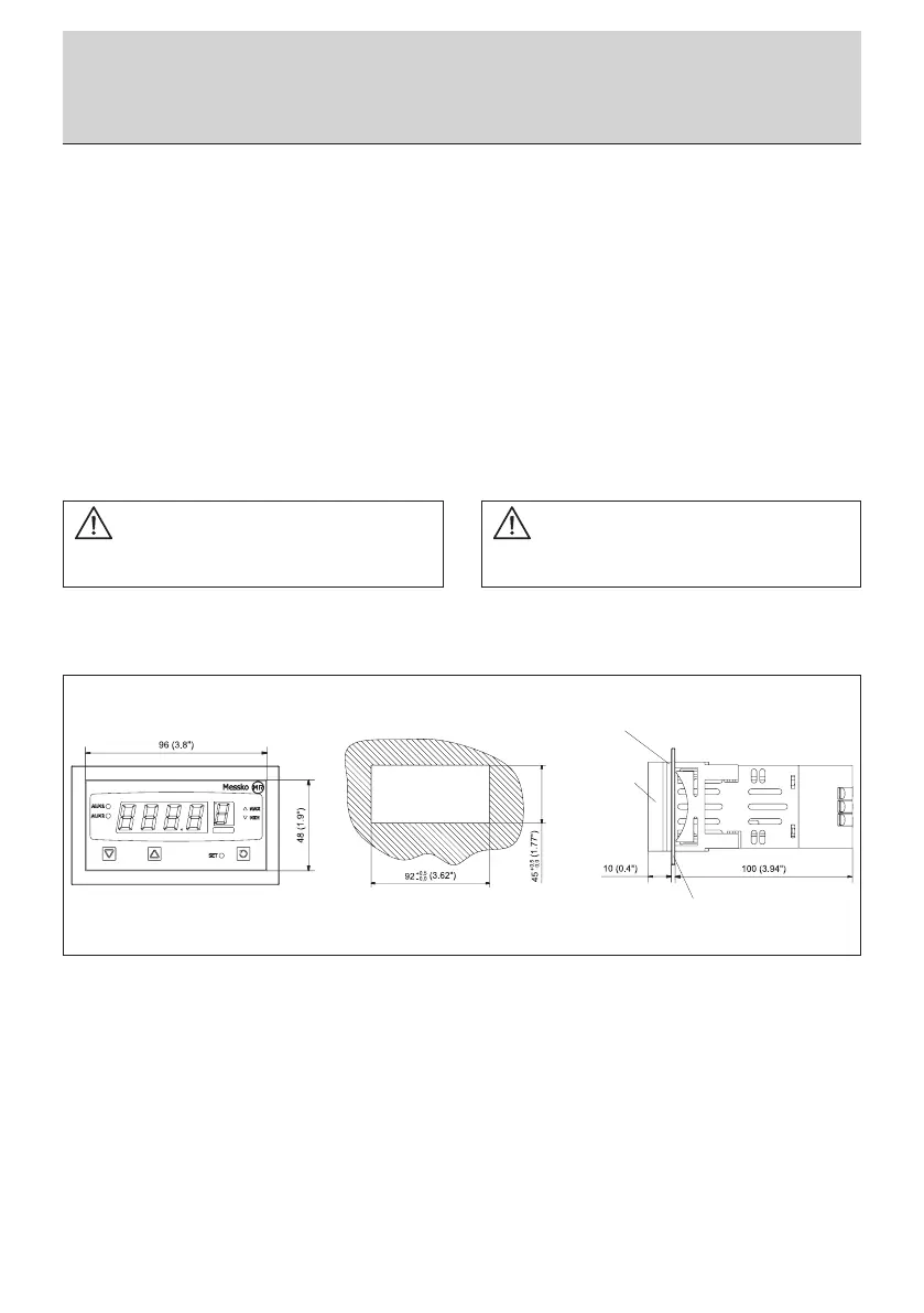
D1272AT 数字指示器可安装在壁厚达 6 mm 的控制板
内。有关控制板切断尺寸,请参见图 2。
The D1272AT digital indicator can be installed in control
panels with a wall thickness of up to 6 mm. For the dimensions
of the control panel cutout, see gure 2.
按照下列要求继续安装设备:
• 将 D1272AT 数字指示器滑入控制板的切口中,确保
指示器的最终位置在正面。然后轻轻地将其按到控制板
上。检查确保控制板密封件定位正确。
• 从尾部开始,将支架框滑到设备上,直至其接触控
制板的背面。然后支架框顶部和底部的支架齿扣入设备
的支架格内。支架框的弹簧必须牢固地按到控制板的背
面。
设备安装之后便可进行连接。
Proceed as follows to install the device:
• Slide the D1272AT digital indicator into the control panel
cutout so that the nal location of the indicator is in front.
Then lightly press it against the control panel. Check to make
sure that the control panel seal is positioned correctly.
• Starting from the back, slide the holder frame over the
device until it touches the back of the control panel. The
holder teeth on the top and bottom of the holder frame will
then snap into the holder grid of the device. The springs of the
holder frame must be pressed rmly against the back of the
control panel.
After the device has been installed, it can be connected.
控制板开孔/
Control panel cutout
控制板/Control panel
控制板密封/
Control panel sealing
操作者前方/
Operator front
图 2/Fig. 2
3 安装/Installation