7
English
OPERATION AND MAINTENANCE
NOTE: The information contained in this Instruction Manual is designed to assist you in the safe
operation and maintenance of the power tool. Some illustrations in this Instruction Manual may
show details or attachments that diff er from those on your own power tool.
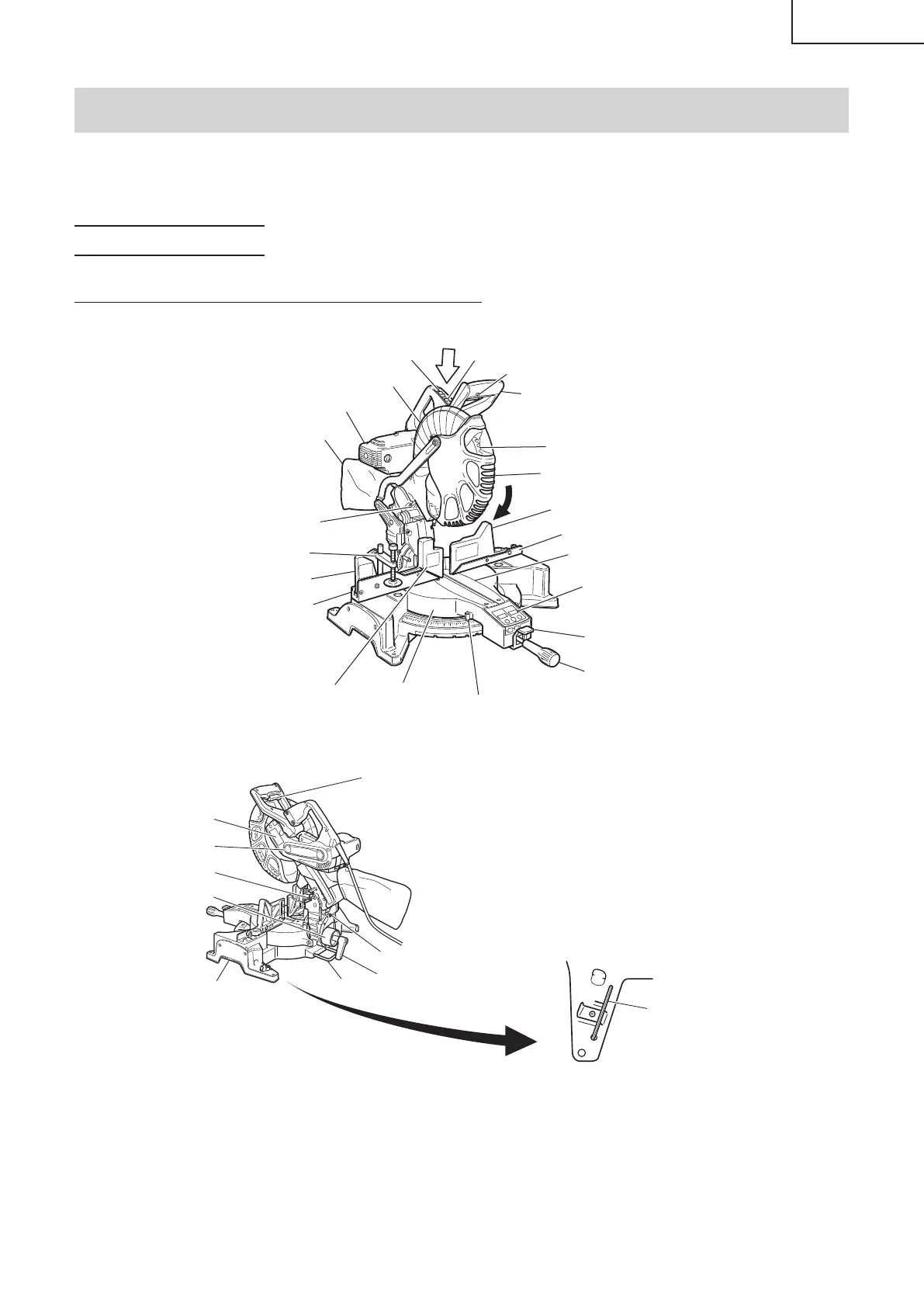
NAME OF PARTS
MODEL C12LDH/MODEL C12FDH
∙
C12FDH(S)
Handle
Head
Lock-off button
Gear case
Dust bag
Motor
Saw blade
Lower guard
Rotation direction
Fence (A)
Sub fence (A)
Sub fence (C)
Fence (B)
Table insert
Digital display
(for C12LDH)
Indicator (A)
(for miter scale)
Lever
Side handle
Turntable
Sub fence (B)
Laser marker
Vise assembly
Switch
(for digital display)
(for C12LDH)
Switch
(for laser marker)
Fig. 1
Trigger switch
4mm hex. bar wrench
Nameplate
Pully cover
Locking pin
Base
Holder (B)
Clamp lever
Set pin
Knob (A)
Fig. 2-a
Fig. 2-b
00BookC12LDHUS.indb700BookC12LDHUS.indb7 2018/11/3016:55:532018/11/3016:55:53
 Loading...