17
meteo – SP89 Manual
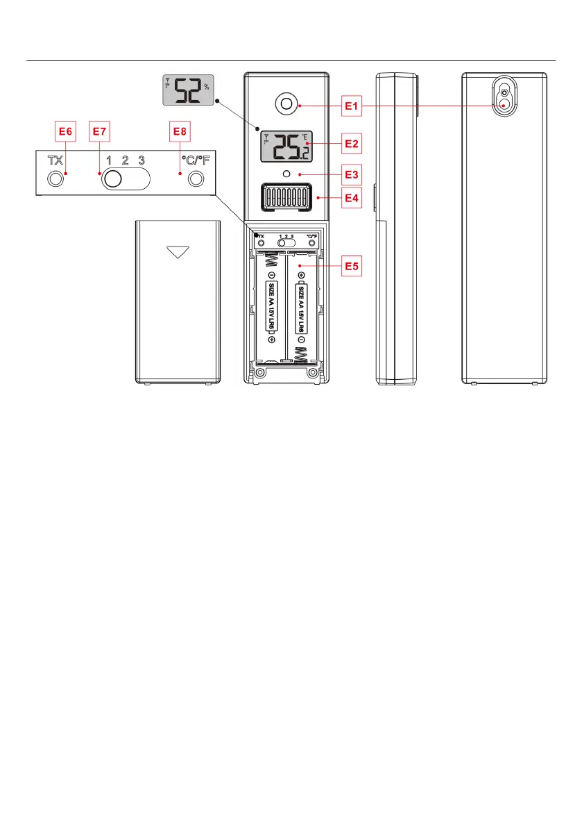
Part E –Exterior
E1: Hanging hole E2: LCD display
E3:
E4: Temperature | Humidity sensing louver
E5: Battery compartment
E6:
Manual transmit signal button “TX”
E7: “CHANNEL 1 or 2 or 3” switch
meteo – SP89 Manual
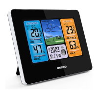
Part C –Exterior
C1:
Hanging hole C2: Battery compartment
C3: USB charging socket C4:
Power supply socket
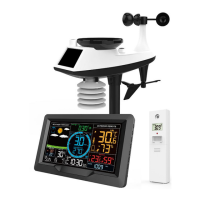
Multi-combination Wireless Remote Sensor Appearance
Part D –Exterior
D1: Solar panel
D2: Rain funnel
D3: Wind cups
D5: Temperature | humidity induction box D6: Wind Directional Vane
D7: Reset button D8: LED indicator
D9: Manual transmit signal button
D11: Support rod D12: Fixed base
D13: Socket head cap screws
D14: Drain vents For rain sensor
D15: North direction mark D16: Rain funnel rotation mark
D17: Large nut for fixing the support rod and the base
Temperature | Humidity Wireless Remote Sensor Appearance