Line Tracer
17
3.1. Tracing Cables in Walls, Ceilings, Floor and Ground, and
Defected Fuses
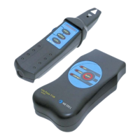
Tracing of Hidden Wires on Non-energized Systems
OFF
Receiver R10K
switched in
capacitive mode
Transmitter T10K
is automatically
in generator mode
Fig. 12. Tracing cable or determination of the belonging fuse on non-energized
installation. The receiver detects the electrical field, caused by the voltage generation of
the transmitter.
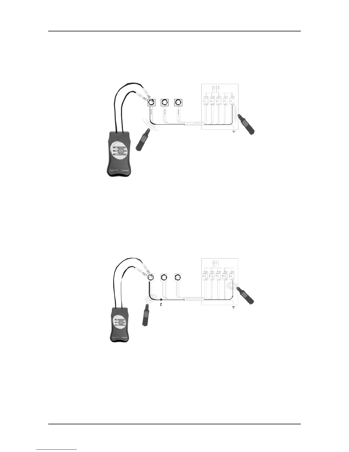
Tracing Cables in Walls, Ceilings, Floor and Ground on Energized Systems
ON
Receiv er R1 0K
switched in
inductive mode
Transmitter T10K
is automatically
in load mode
Fig. 13. Tracing cable or determination of the belonging fuse on energized installation.
The receiver detects the electromagnetic field caused by load current of the transmitter.
Note: The tracing distance can be increased, if the transmitter is connected to N of one
wall socket and L of another wall socket.