Line Tracer
8
2. Operation principle
2.1. Fundamentals
Decision for tracing mode selection depends on the object, its structure, energized state
and many other reasons. Understanding the electric and magnetic field characteristics
leads to selecting the most applicable method. For most of the applications good
sensitivity is required, especially when the searched conductor is located far away.
Contrary to this the minimum sensitivity is required for selection of a searched
conductor in a group of similar conductors. The sensitivity will be in-between for finding
appropriate protective device (fuse) or conductors in the proximity.
The basis for all tracing of this kind is that the traced object is electrically conductive.
Current loops and electromagnetic field
Magnetic field is always present around current carrying conductors.
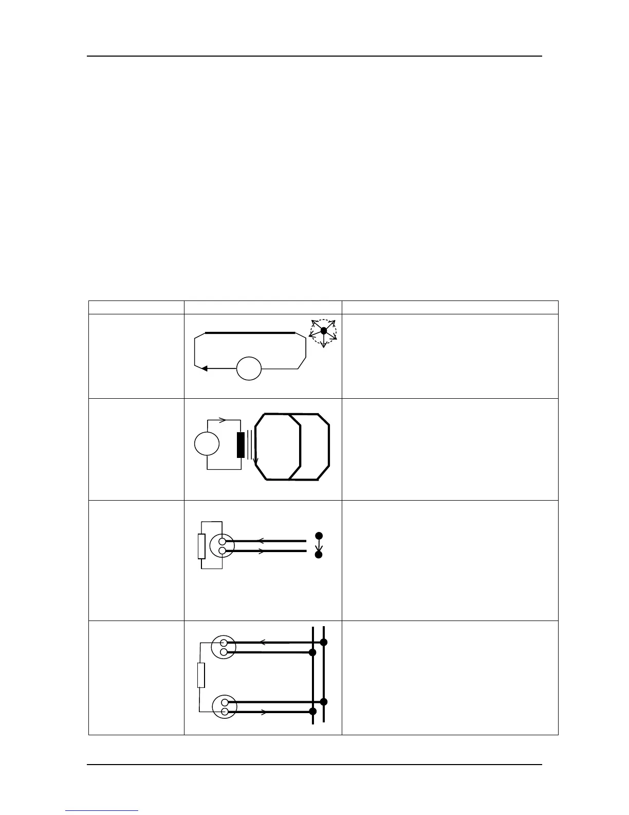
Example Basic circuit Description
Free conductor
H
I
- magnetic field (H) is distributed
around conductor
- current (I) is limited to internal
source capability
- INDuctive sensor is applicable for
tracing
Metallic loops
nI
CT
1
2
- current is transformed with a clamp
transformer (CT) n times to n
⋅I
- always the shortest path (e.g. 1)
carry maximum current and is
traceable
- INDuctive sensor is applicable for
tracing
Single wall
socket
connection
I
ALS
L
N
H
- active load source (ALS) generates
current
- major part of magnetic field (H) is
concentrated in a gap between
conductors
- rest of the field depends on wire
distance
- INDuctive sensor is applicable for
tracing (up to a few cm distance)
Two wall
sockets with
different
conduits to the
point of
common
coupling
I
ALS
L
N
I
- active load source (ALS) generates
current
- magnetic field is distributed around
each of current carrying conductors
- INDuctive sensor is applicable for
tracing