Doc# 0296-0018 • REV R (July 2017) Page 54 of 61
Stac Linearity Test
This procedure is for checking the displacement probe output over its total measurement range, from
minimum gap to maximum gap. The Dial Micrometer Aachment and Mounng Fixture is required for
this test.
Step 1. Install the Mounng Fixture and Target.
Step 2. Install the Dial Micrometer if it not already aached to the Mounng Fixture.
Step 3. Set the gap to approximately 40 Mils.
Step 4. Install the Probe “Holder Tube” part of the Kit by aaching it to the Dial Micrometer end.
Step 5. Select the holder tube based on the diameter of the Probe being tested. Use the set screw to
lock it in place.
Step 6. Set The Dial Micrometer to exactly 40 Mils.
Step 7. Raise the probe in the holder while watching for a gap voltage of -8 VDC (based on 200 mV/Mil).
Step 8. Lock the probe in place using the set screw being sure to maintain the -8 VDC reading.
Step 9. Use the TTS in the DC voltmeter mode to get this reading. Step 10. Set the Dial Micrometer to 5
Mils on the dial but do not contact the target.
Step 11. Read and record the voltmeter reading.
NOTE: When moving to a new reading on the Dial Micrometer, be very careful not to go past the new
reading. It is desirable to take all readings in one direcon without backing up. There is a slight hyster-
esis that occurs when changing direcons.
Step 12. Set the Dial Micrometer to 10 Mils on the dial.
Step 13. Read and record the voltmeter reading.
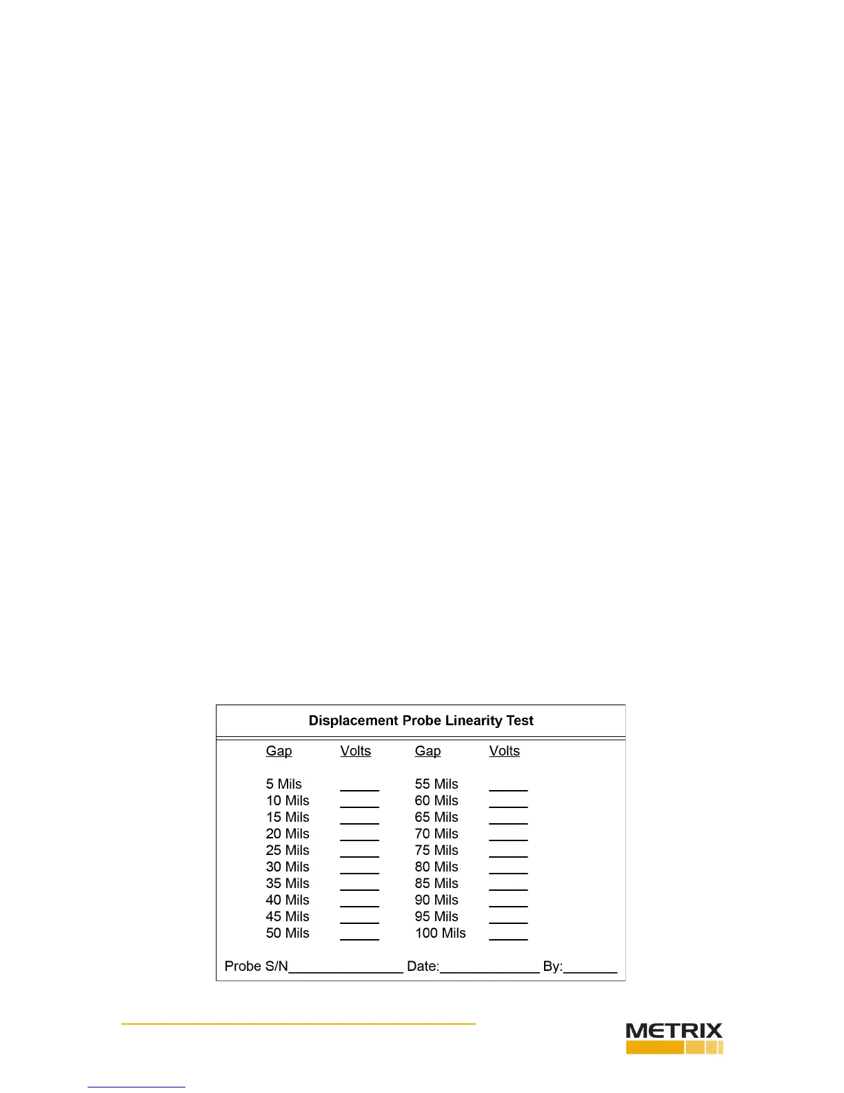
Step 14. Connue reading and recording data through the enre range as listed on the Sample Data
Sheet.
 Loading...

