Doc# 0296-0018 • REV R (July 2017) Page 51 of 61
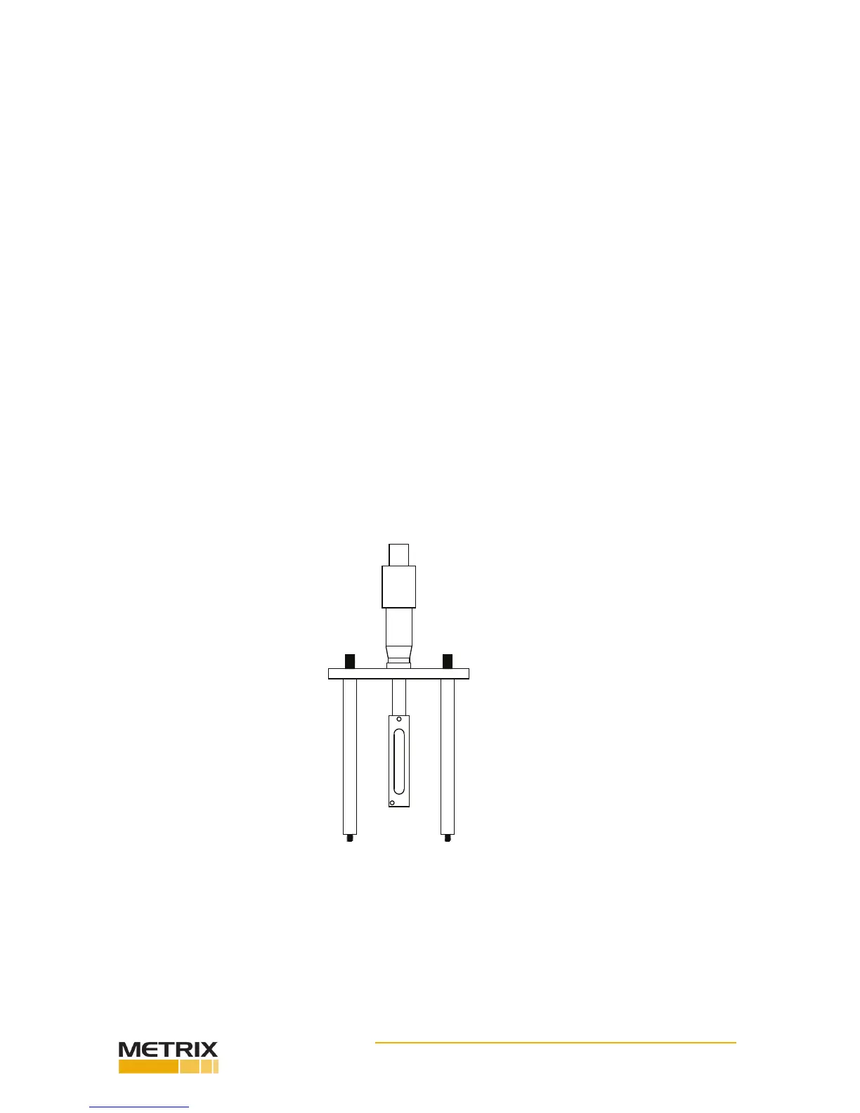
FIG. 5-10 DISPLACEMENT PROBE MOUNTING FIXTURE WITH DIAL MICROMETER
Dynamic Sensivity Test
The test measures the sensivies of the displacement probe at the various gaps, typically; 30, 40, 50
and 60 mils.
Step 1. Turn on the Power Switch.
Step 2. Install the Target by screwing the target into the reference accelerometer unl it is nger ght.
Be sure to use the spanner wrench when installing.
Step 3. Install the displacement probe mounng xture onto the TTS and connect the displacement
probe system as shown in Chapter 3, Installaon, Displacement Probe, pg 3-5.
NOTE: Make sure the Displacement Probe system is a matched set consisng of a Probe, Oscillator/
Demodulator and interconnecng Cable.
Step 4. Install the Probe in the Mounng Fixture (See Fig. 5-10) and set the Probe Gap (distance from
the probe to the target), by reading the DC voltage output listed below. It is important to understand the
electrical gap and the mechanical are dierent. The Probe is encapsulated with protecve material and
epoxy. If a feeler gage is used to set the gap a dierent output voltage could be read.
• 30 Mils = 6 VDC Based on 200 mV/Mil
• 40 Mils = 8 VDC
• 50 Mils = 10 VDC
• 60 Mils = 12 VDC
 Loading...

