4
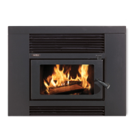
Assembling the replace insert’s rebox
The replace insert rebox is supplied in a heavy duty
carton and is secured to a timber pallet. Having removed
the cardboard, timber and polystyrene packaging and
familiarised yourself with Diagram 1 on page 2, proceed
as follows: -
• Remove from within the rebox the plastic bag
containing the bolt kit, two rebricks wrapped in a
cardboard wrapper and the top bafe assembly.
• A “spacer” washer has been pre-tted and taped to
the top door hinge pin on the left hand side of the
rebox (Refer Inset A, Diagram 1) remove this tape.
• Take the boxed door you previously removed from the
centre of the fascia and unpack it. Taking the door in
both hands with the spindle end in your right hand and
outer face of the door facing you, attach the door to
the rebox as follows: -
- With the door in a 45 degrees open position, allow the
lower hinge pin on the bottom left hand side of the
rebox to pass into the hole provided in the bottom of
the door frame.
- Lift the door until the top of the door frame passes over
the top hinge pin, then align the hole provided on the
top face of the door frame and lower it down over the
top hinge pin.
- Take the door handle from the plastic bag and screw it
onto the door spindle by turning it clockwise.
• Unwrap the two rebricks from the cardboard wrapper
and t the side bricks to each side of the rebox.
Location lugs are tted to the base and rear of the
rebox to retain the side bricks in position, refer
Diagram 3 on the opposing page.
• Remove the “cabinet top” which is packed inverted
on top of the rebox and t it into position “over” the
cabinet sides as detailed in Diagram 1. Ensure the rear
edge is tted correctly as shown in Diagram 1, Inset
“B”. The rear edge of the cabinet top must t “into” the
slot provided. Using two of the self tapping screws from
the plastic bag, secure the cabinet top in place. Note,
this panel can be tted at two height’s, if the height of
the replace opening will allow, t the cabinet top in
the higher position, t screws from “inside” the cabinet
facing out.
• Ensure the insulating blanket is in position on the top of
the cabinet.
• Remove the four speed clip nuts from the plastic bag
and t them to the holes provided in the front edge of
the cabinet as shown in Diagram 1.
• Next you need to t the top bafe, refer to Diagram
3 on the opposing page 5 and proceed with the
instructions below that apply to the model you are
assembling: -
LTD Insert Firebox
This model has a two piece top bafe which locates onto
six lugs provided on the side walls of the rebox’s upper
chamber, as detailed in Diagram 3 on page 5. The rear
bafe section is 6mm folded steel and has a location pin
tted to its front top surface. Fit this rear bafe through the
door opening and into position in the upper chamber of
the rebox. It is supported on the rear four support lugs
and must be hard back against the rear of the rebox with
the locating pin facing upward and towards the front.
Next, locate the front bafe which is a combination bafe
comprising of a 6mm steel plate with a promet (white
board) front extension. Fit this bafe through the door
opening and into position, ensuring the hole provided on
its rear edge is positioned over the locating pin tted to the
rear bafe.