2.1 Mode of operation of the membrane pump
■■■■■■■■■■■■■■■■■■■■■■
6
■■■■■■■■
2 Overview of the instrument
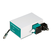
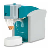
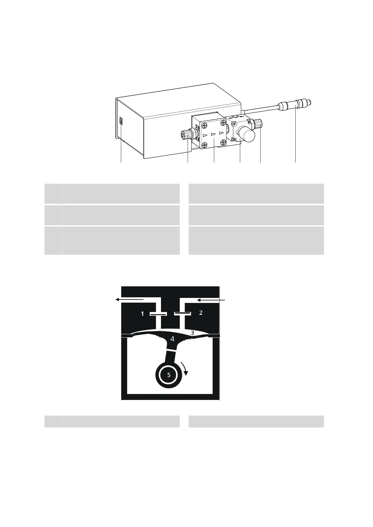
Figure 1 Front 823 Membrane Pump Unit
1
Status LED
For displaying the operating state.
2
Inlet connector
With union nut for the aspiration tubing.
3
Membrane pump
With arrows to indicate the flow direction.
4
Pressurizing valve
5
Outlet connector
With union nut for the drainage tubing.
6
Connection cable
With M8 plug for connection to a Sample
Processor.
2.1 Mode of operation of the membrane pump
Figure 2
Mode of operation of the membrane pump
1
Outlet valve
2
Inlet valve