■■■■■■■■■■■■■■■■■■■■■■
Table of figures
■■■■■■■■
V
Table of figures
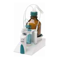
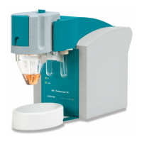
Figure 1 Front 823 Membrane Pump Unit ....................................................... 6
Figure 2 Mode of operation of the membrane pump ...................................... 6
Figure 3 Connecting the tubings ..................................................................... 9
Figure 4 Screwing the union nuts tightly ......................................................... 9
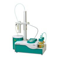
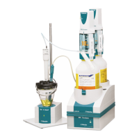
Figure 5 823 Membrane Pump Unit connected directly to the Sample Pro-
cessor ............................................................................................. 10
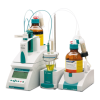
Figure 6 823 Membrane Pump Unit via the Remote Box and 731 Relay Box .. 11