Overview of equipment
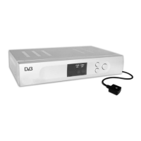
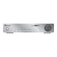
Front side of the receiver
1
- Infrared sensor for the signals of the
remote control
2
LED POWER LED is illuminated if the receiver is
switched on or in standby mode
3
LED STBY
ON
LED is only illuminated if the receiver is in
standby mode
4
CH+ key Switches to the next higher channel
location
Cursor moves up
5
CH- key Switches to the next lower channel
location
Cursor moves down
6
Standby Switches on and switches to the standby
mode
Rear side of the receiver
1
LNB IN LNB connection for the antenna cable
2
IF OUT LNB connection for a second satellite
receiver
3
VCR (output) SCART connection for the video set
4
TV (output) SCART connection for the TV set
5
RS 232 Serial port
6
DC IN 12V Connection 12V/power pack
7
SPDIF Digital coaxial audio output (COAXIAL)
8
AUDIO L Analogue audio connection L(left)
9
AUDIO R Analogue audio connection R(right)
10
IR EXT Infra red extension socket
4