SECTION 3 - M. FRAME, ADJ. RING, TRAMP REL. & CLRNG JACK ASSY
3-26
MP SERIES CONE CRUSHER TECHNICAL REFERENCE MANUAL
3. Place the adjustment ring assembly onto the
main frame so that the clamping cylinder
hose connection is located opposite the
countershaft box. As the adjustment ring is
lowered over the main frame pins, rotate the
ring in a clockwise direction so the main
frame pin bushings in the adjustment ring
touch the main frame pins as shown in
Figure 3-21. Then lower the ring in this
position and allow it to seat on the frame.
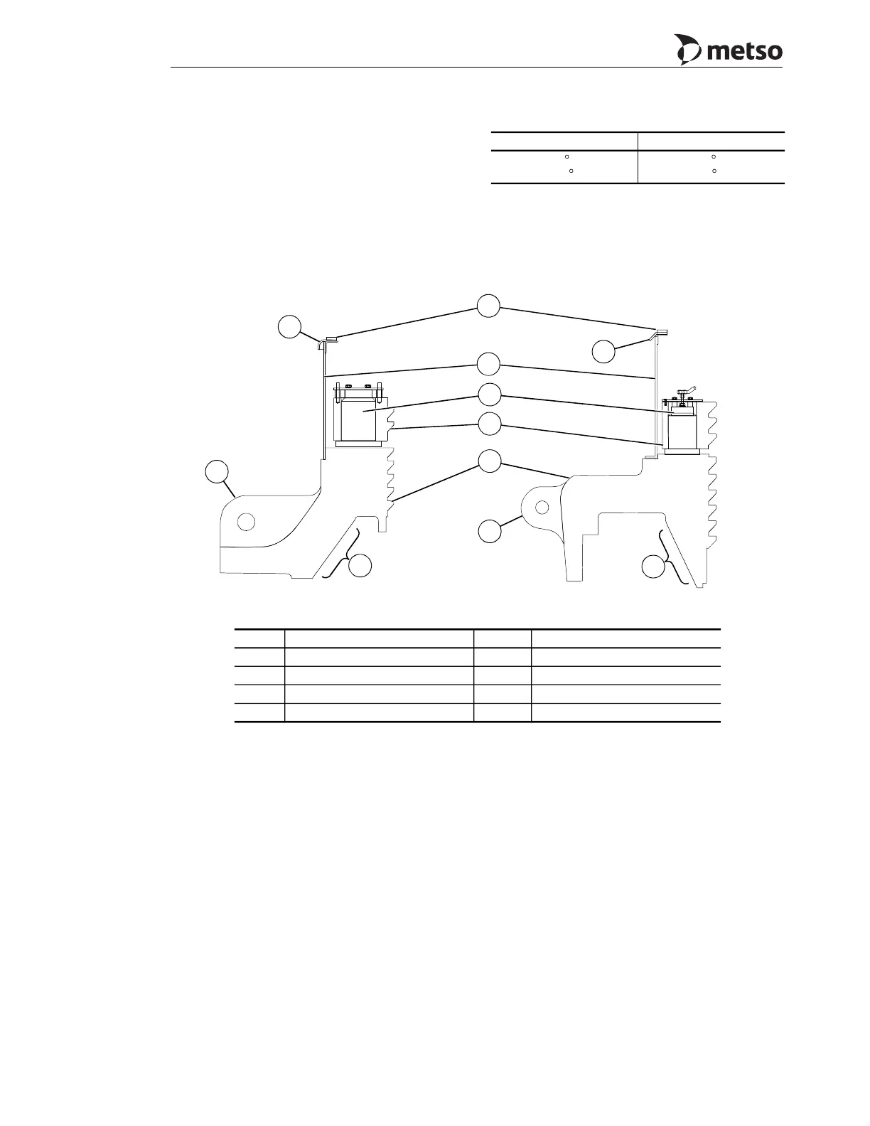
Figure 3-19 Temperature Differences Required
to Install Frame Ring
Figure 3-20 Adjustment Ring Assembly
MP800 MP1000
56
C
(101
F)
50
C
(90
F)
Callout Description Callout Description
1 Adjustment cap seal 5 Clamping cylinder
2 Lifting ear 6 Clamping ring
3 Clamp segment 7 Adjustment ring
4 Dust shell 8 Adjustment Ring seat area
3
1
2
2
7
6
5
8
1
4
8
MP800 MP1000
 Loading...