SECTION 2 - GENERAL INSTALLATION INFORMATION
MP SERIES CONE CRUSHER TECHNICAL REFERENCE MANUAL
2-5
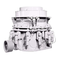
Table 2-1 MP800 Clearance Dimensions (refer to Figure 2-3)
Callout Description
Standard
mm (in.)
Short Head
mm (in.)
A Main frame flange
1750
(5' 8-7/8")
1750
(5' 8-7/8")
B Main frame flange
1750
(5' 8-7/8")
1750
(5' 8-7/8")
C Main frame flange
1750
(5' 8-7/8")
1750
(5' 8-7/8")
D Main frame hub diameter
875
(2' 10-7/16")
875
(2' 10-7/16")
E To bottom of main frame hub
280
(11")
280
(11")
F To bottom of oil piping
762
(2' 6")
762
(2' 6")
G To top of bowl drive pinion guard
3385
(11' 1-1/4")
3385
(11' 1-1/4")
H Adjustment ring maximum diameter
4550
(14' 11-1/8")
4550
(14' 11-1/8")
J Clearance required for removing countershaft assembly
3881
(12' 8-13/16")
3881
(12' 8-13/16")
K To end of countershaft
2538
(8' 3-15/16")
2538
(8' 3-15/16")
L Maximum height to top of feed hopper
3860
(12' 8")
3752
(12' 3-3/4")
M Inside diameter of feed hopper
2210
(7' 3")
2110
(6' 11-1/16")
N To top of feed plate
2758
(9' 0-5/8")
2758
(9' 0-5/8")
O Overall height of bowl assembly
2133
(7' 0")
1964
(6' 5-5/16")
P Adjustment cap maximum diameter
3170
(10' 4-13/16")
3170
(10' 4-13/16")
Q Clearance required for removing bowl assembly
5518
(18' 1-1/4")
5399
(17' 8-9/16")
R Overall height of head assembly
2110
(6' 11-1/16")
2110
(6' 11-1/16")
S Head or mantle maximum diameter
2114
(6' 11-1/4")
2083
(6' 10")
T Clearance required for removing head assembly
5495
(18' 0-3/8")
5545
(18' 0-3/16")
U Tramp release side to side
4280
(14' 0-1/2")
4280
(14' 0-1/2")
V Additional upward travel due to clearing stroke
163
(6-7/16")
163
(6-7/16")
 Loading...