Sonicator 740 Instruction Manual— Rev.G_06/28/12
35
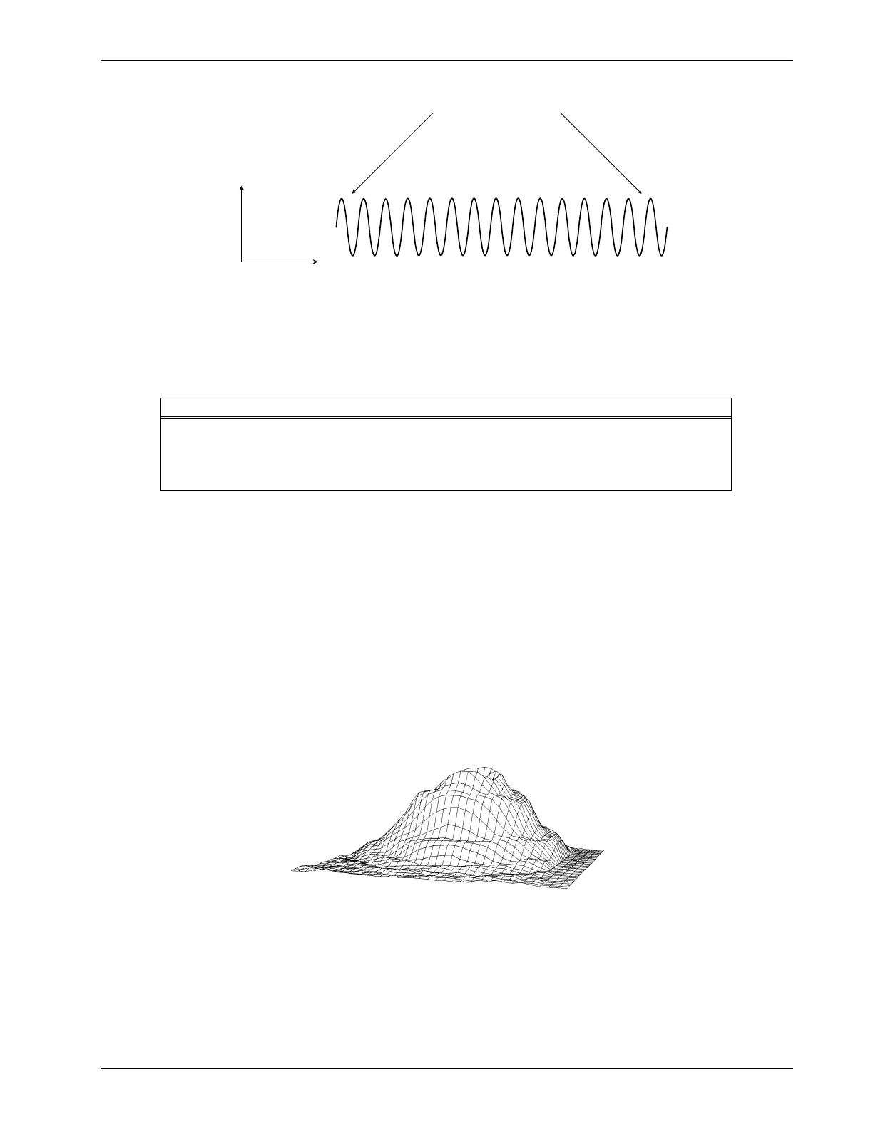
In the continuous mode, the power is on at least 95% of the time the timer is
running. The continuous mode waveform is shown below:
Time
Output
1, 3.2 or 3.3 MHz
Figure 9.4—Continuous Waveform
9.3 Ultrasonic Applicator Specifications:
Piezoelectric discs: The output transducer utilizes a barium titanate disc with a specially coated
face.
Individual Applicator Specification:
Applicator Part Number Frequency Effective Radiating Area
ME 7413 1 MHz ±10% 5 cm² ±20%
ME 7413 3.2 MHz ±10% 5 cm² ±20%
ME 7410 1 MHz ±10% 10 cm² ±20%
ME 7431 3.3 MHz ±10% 1 cm² ±20%
Beam type: Collimating
Maximum beam
non–uniformity ratio: 6:1
Spatial Pattern: The applicator produces a collimated (cylindrical) beam with an area of 1, 5
or 10 cm², measured 5 mm from the ceramic disc surface when the radiation
is emitted into the equivalent of an infinite medium of distilled, degassed
water at 30° C, and with line voltage variations in the range of the rated
value.
The beam of the applicator is circular in all planes parallel to the applicator
face. A few inches from the face, it is a single smooth bell-shaped curve.
Nearer the face the pattern varies more due to phase cancellations. Sample
curves measured in the far field from the surface are shown in Figures 9.5,
9.6, 9.7 and 9.8.
Figure 9.5—10 cm² Applicator (1 MHz), ME 7410,—Three Dimensional Beam Pattern