Crimpspleißschutz
Art.-Nr. 15090401-E
Verpackungseinheit 12 Stück
Art.-Nr. 15090401-I
Verpackungseinheit 150 Stück
METZ CONNECT GmbH
Im Tal 2 | 78176 Blumberg | Germany | Ph. +49 7702 533-0 | Fax +49 7702 533-433
Montageanleitung siehe / Mounting instruction see / notice de montage voir www.metz-connect.com
8
5
7
6
Ë
Ê
Zubehör
D E
F G
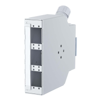
OpDAT REG Zugentlastung
Art.-Nr. 150240M20Z-E
Verpackungseinheit 1 Stück
D
E
OpDAT REG Strain Relief
Part number 150240M20Z-E
Packing unit 1 piece
D
OpDAT REG Décharge de traction
Référence 150240M20Z-E
Unité d‘emballage 1 pièce
D
Accessories Accessoires
Crimp Splice Protection
Part number 15090401-E
Packing unit 12 pieces
Part number 15090401-I
Packing unit 150 pieces
E
Protection d‘épissures crimp
Référence 15090401-E
Unité d‘emballage 12 pièces
Référence 15090401-I
Unité d‘emballage 150 pièces
E
OpDAT Pigtails SC
9/125 µm (OS2) Art.-Nr. 150Q1CO0020E
50/125 µm (OM2) Art.-Nr. 150B1CO0020E
50/125 µm (OM3) Art.-Nr. 150M1CO0020E
50/125 µm (OM4) Art.-Nr. 150N1CO0020E
Verpackungseinheit 12 Stück
F
OpDAT ST-D Kupplung
Ph-Br MM Art.-Nr. 15090041-I
Keramik SM/MM Art.-Nr. 150900D1-I
Verpackungseinheit 12 Stück
G
OpDAT Pigtails SC
9/125 µm (OS2) Part number 150Q1CO0020E
50/125 µm (OM2) Part number 150B1CO0020E
50/125 µm (OM3) Part number 150M1CO0020E
50/125 µm (OM4) Part number 150N1CO0020E
Packing unit 12 pieces
F
OpDAT Pigtails SC
9/125 µm (OS2) Référence 150Q1CO0020E
50/125 µm (OM2) Référence 150B1CO0020E
50/125 µm (OM3) Référence 150M1CO0020E
50/125 µm (OM4) Référence 150N1CO0020E
Unité d‘emballage 12 pièces
F
OpDAT ST-D Adapter
Ph-Br MM Part number 15090041-I
Ceramic SM/MM Part number 150900D1-I
Packing unit 12 pieces
G
OpDAT Coupleur ST-D
Ph-Br MM Référence 15090041-I
Céramique SM/MM Référence 150900D1-I
Unité d‘emballage 12 pièces
G
9 10
Bild 5
LWL-Stammkabel ca. 1,0 - 1,2 m abmanteln (Bündelader ca.
5 cm stehen lassen). Kevlar oder Zugentlastungselement an
der Zugentlastung fixieren. An der Gehäuseober- und unter-
seite kann jeweils ein Stammkabel zugeführt werden (schräg
oder gerade). Eine zweite M20-Verschraubung mit Zugent-
lastung ist als Zubehör erhältlich.
Figure 6
Wrap insulating tape (not included in delivery) around the pig-
tails in positions Ê and Ë. Secure the pigtails to the splice tray
in position Ê with one of the cable ties.
Wrap also insulating tape around the fibers of the main cable
and secure them at the opposite side of the splice tray with
one of the cable ties.
Figure 7
Splice and store the fiber reserve in the splice tray.
Figure 8
Snap the OpDAT REGplus onto the rail TH35 (standard
mounting).
Other mounting positions
Figure 9
Unscrew the rail fixation.
Figure 10
Screw the rail fixation on the side wall of the housing for a
horizontal or vertical mounting to the rail.
Figure 6
Enrouler les pigtails avec du ruban isolant (ne pas inclus dans
l‘emballage) aux positions marquées Ê et Ë. Retenir les
pigtails par serre-câble au plateau d‘épissures à la position Ê.
Enrouler aussi les fibres du câble principal avec du ruban
isolant et les retirer par serre-câble sur le côté opposé du
plateau d‘épissures.
Figure 7
Epissurer et placer la réserve de fibres dans le plateau
d‘épissures.
Figure 8
Encliqueter OpDAT REGplus sur le rail TH35 (montage
standard).
D‘autres positions de montage
Figure 9
Dévisser la fixation pour rail.
Figure 10
Visser la fixation pour rail sur le panneau latéral pour un
montage sur rail horizontal ou vertical.
DEUTSCH
de
ENGLISH
en
FRANÇAIS
fr
WARNUNG
Bündelader auf keinen Fall unter der
Zugentlastung fixieren!
Bild 6
Pigtails mit Isolierband (nicht im Lieferumfang enthalten) an
den abgebildeten Positionen Ê und Ë umwickeln. An Position
Ê die Pigtails mit einem der Kabelbinder an der Spleißablage
abfangen.
Fasern des Stammkabels ebenfalls mit Isolierband umwickeln
und mit einem weiteren Kabelbinder an der gegenüberliegen-
den Seite der Spleißablage abfangen.
Bild 7
Spleißen und den Faservorrat in der Spleißablage ablegen.
Bild 8
OpDAT REGplus auf die Tragschiene TH35 aufrasten.
(Standardmontage).
Weitere Montagepositionen
Bild 9
Tragschienenbefestigung abschrauben.
Bild 10
Tragschienenbefestigung auf die Seitenwand schrauben für
horizontale oder vertikale Montage auf der Tragschiene.
ATTENTION
Do not fix the loose tube under the strain relief!
ATTENTION
Jamais fixer les fibres à structure serrée sous la
décharge de traction !
Figure 5
Strip the insulation from the fiber optic cable by about 1.0 to
1.2 m (leave about 5 cm of the loose tube). Fix Kevlar or strain
relief element at the strain relief. Cable feed to the housing
from top or bottom (straight or inclined). A second M20 cable
gland with strain relief is available as accessory.
Figure 5
Dénuder le câble fibre optique d‘environ 1,0 à 1,2 m (laisser
environ 5 cm des fibres à structure serrée). Fixer le Kevlar ou
l‘élément de décharge de traction à la décharge de traction.
Un câble peut arrivé par le haut et un par le bas du boîtier
(horizontale ou en diagonale). Un deuxième presse-étoupe
M20 est disponible en accessoire.
 Loading...