EasyManuals Logo

Meyer Sound CQ-2 User Manual

Meyer Sound CQ-2
16 pages
To Next Page IconTo Next Page
To Previous Page IconTo Previous Page
Page #10 background imageLoading...
Page #10 background image
10
Verifying Polarity
Incorrect driver polarity impairs system performance
and may damage the drivers. All Meyer Sound
loudspeakers are shipped with the drivers in correct
alignment. However, if the driver or circuit wiring has
been removed or disassembled in any loudspeaker in
a system for any reason, check the polarity between
adjacent loudspeakers and between drivers in the
same cabinet.
Polarity Between Adjacent Loudspeakers
Use the following test procedure to verify the polarity
between adjacent loudspeakers of the same type:
1. Position two loudspeakers adjacent to each other.
2. Place a measurement microphone six ft from the
speakers on the axis between them.
3. Connect a signal source to one speaker and note
the frequency response and overall level.
4. Apply the same signal to the second speaker with
the first speaker still connected.
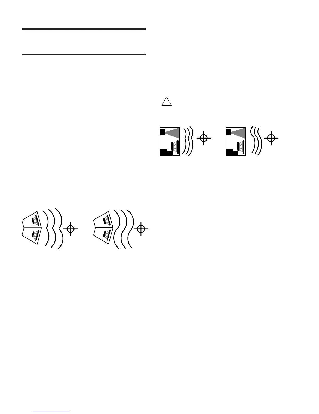
Correct polarity causes
acoustic addition
Opposite polarity causes
acoustic cancellation
Top view of adjacent speakers with
measurement microphone
The polarity is correct if the frequency response
remains constant with a significant increase in
amplitude. Broadband cancellation (decreased overall
level) indicates polarity reversal.
Driver Polarity in the Same Loudspeaker
Use the following test procedure to verify polarity
between drivers in the same loudspeaker:
1. Place a monitoring microphone three ft from the
front of the loudspeaker at the midway point
between the low and high frequency drivers.
2. Connect a signal source to the loudspeaker and
note the frequency response.
!
Since polarity reversal causes excessive driver
excursion at high source levels, use moderate levels
when conducting this test.
Drivers with correct
polarity cause acoustic
addition
Drivers with reversed
polarity cause acoustic
cancellation
The polarity is correct if the frequency response is smooth
through the crossover region (±4 dB 600 Hz – 1 kHz).
Severe cancellation in the crossover region indicates
polarity reversal.

Questions and Answers:

Question and Answer IconNeed help?

Do you have a question about the Meyer Sound CQ-2 and is the answer not in the manual?

Meyer Sound CQ-2 Specifications

CQ-1

Acoustical IconAcoustical
frequency response± 4 dB 40 Hz – 18 kHz
phase response± 90° 50 Hz – 16 kHz
maximum peak SPL136 dB
dynamic range> 110 dB
Coverage IconCoverage
-6 dB points horizontal80° (500 Hz – 16 kHz)
-6 dB points vertical40° (1.5 kHz – 12 kHz)
-10 dB points horizontal100° (500 Hz – 16 kHz)
-10 dB points vertical50° (1.5 kHz – 12 kHz)
Transducers IconTransducers
low frequency transducer15” diameter MS-15 cone
high frequency transducer4” diaphragm MS-2001CQ horn compression driver
Acoustical Crossover Point IconAcoustical Crossover Point
crossover point700 Hz
Amplifiers IconAmplifiers
typecomplementary power MOSFET output stages class AB/H
burst capability1240 Watts (620 Watts/channel)
THD, IM, TIM< .02 %
Audio Input IconAudio Input
input impedance10 kΩ electronically balanced
connector typeXLR (A-3) male and female
nominal input level+4 dBu (1.23 Vrms)
AC Power IconAC Power
connector250 V NEMA L6-20P / IEC 309 Twistlock male receptacle
voltage selection85 – 134 V / 165 – 264 V; 50 Hz / 60 Hz
max continuous RMS current 115 V8 A
max continuous RMS current 230 V4 A
max burst RMS current 115 V15 A
max burst RMS current 230 V8 A
max peak current during burst 115 V22 Apk
max peak current during burst 230 V11 Apk
inrush current< 12A @115V
Physical IconPhysical
dimensions21” W x 30” H x 22 1/2” D
weight130 lb (59 kg)
shipping weight150 lb (68 kg)
enclosure/finishAll birch plywood/black textured
protective grillPerforated steel grill, charcoal-grey foam
rigging fittingsFour aircraft pan fittings (two on top and bottom)
working load per fitting500 lb

CQ-2

Acoustical IconAcoustical
frequency response± 4 dB 40 Hz – 18 kHz
phase response± 90° 50 Hz – 16 kHz
maximum peak SPL139 dB
dynamic range> 110 dB
Coverage IconCoverage
-6 dB points horizontal50° (800 Hz – 12 kHz)
-6 dB points vertical40° (1.5 kHz – 12 kHz)
-10 dB points horizontal60° (800 Hz – 12 kHz)
-10 dB points vertical50° (1.5 kHz – 12 kHz)
Transducers IconTransducers
low frequency transducer15” diameter MS-15 cone
high frequency transducer4” diaphragm MS-2001CQ horn compression driver
Acoustical Crossover Point IconAcoustical Crossover Point
crossover point900 Hz
Amplifiers IconAmplifiers
typecomplementary power MOSFET output stages class AB/H
burst capability1240 Watts (620 Watts/channel)
THD, IM, TIM< .02 %
Audio Input IconAudio Input
input impedance10 kΩ electronically balanced
connector typeXLR (A-3) male and female
nominal input level+4 dBu (1.23 Vrms)
AC Power IconAC Power
connector250 V NEMA L6-20P / IEC 309 Twistlock male receptacle
voltage selection85 – 134 V / 165 – 264 V; 50 Hz / 60 Hz
max continuous RMS current 115 V8 A
max continuous RMS current 230 V4 A
max burst RMS current 115 V15 A
max burst RMS current 230 V8 A
max peak current during burst 115 V22 Apk
max peak current during burst 230 V11 Apk
inrush current< 12A @115V
Physical IconPhysical
dimensions21” W x 30” H x 22 1/2” D
weight130 lb (59 kg)
shipping weight150 lb (68 kg)
enclosure/finishAll birch plywood/black textured
protective grillPerforated steel grill, charcoal-grey foam
rigging fittingsFour aircraft pan fittings (two on top and bottom)
working load per fitting500 lb

Related product manuals