4
Introduction
The Meyer LD-1A Line Driver combines functions
previously accessed on the control electronics units for
externally amplified Meyer loudspeakers with new
features, and locates them in a self-contained device
accessible to the sound engineer during setup and
performance. The LD-1A
• integrates different types of Meyer self-powered
speakers into a full-range main system;
• provides gain, mute, and optimized EQ controls
for six auxiliary systems;
• maintains signal integrity for long cable paths.
Channels 1 and 2, equipped to control the main system,
each have:
• a gain control, mute switch, and crossover
function;
• separate Mid-Hi, DS-2 (mid-bass), and Sub
output controls;
• a male XLR Loop connector to route the input
signal to an auxiliary channel or another device.
The six auxiliary channels (3–8) control down-fill, front-
fill, and delay systems. Auxiliary channels can also be
used to divide a main system into subsystems, allowing
independent signal levels for speakers directed at different
audience locations. Each auxiliary channel has a mute
switch, gain control, and Lo Cut and Array EQ filters. All
eight channels are fully independent from each other.
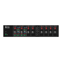
The LD-1A occupies two rack spaces and is constructed
with a 16-gauge steel chassis and
1
/8” aluminum rack
ears. This rugged design provides protection from
accidental impact, magnetic isolation from nearby
devices, and EMI immunity.
Meyer Speaker Types
The following Meyer self-powered speakers are mentioned
in this document.
MSL-4 Self-powered mid-hi speaker
CQ Series Self-powered mid-hi speaker
DS-2P Self-powered mid-bass speaker
650-P Self-powered subwoofer
PSW-2 Self-powered subwoofer
Audio Input
The LD-1A presents a 10 kOhm balanced input imped-
ance to a three-pin XLR connector wired with the follow-
ing convention:
Case — Earth (AC) ground and chassis
Pin 1 — Earth (AC) ground and chassis
Pin 2 — Signal
Pin 3 — Signal
The LD-1A is balanced in and out, and consequently has
no hot (+) pin. Pins 2 and 3 carry the input as a differential
signal. Use standard audio cables with XLR connectors
for balanced signal sources.
The audio input signal should always be applied between
pins 2 and 3. Pin 1 is connected to chassis and acts as a
safety and current bleed to earth for the EMI and ESD
interference coupled onto the shield of the input cable.
Pin 1 is therefore a noisy ground, and connecting an audio
signal between pins 1 and 2, or pins 1 and 3, results in
a noisy audio signal.
Most modern balanced audio sources (electronically
balanced or transformer output) conform to the wiring
convention described above and interface correctly with
the LD-1A. However, an audio source may produce noise
if it connects pin 1 to a quiet internal audio ground, and
is then connected to pin 1 of the LD-1A (chassis/earth).
To alleviate this noise, try disconnecting pin 1 (or the
cable shield) of the audio source.
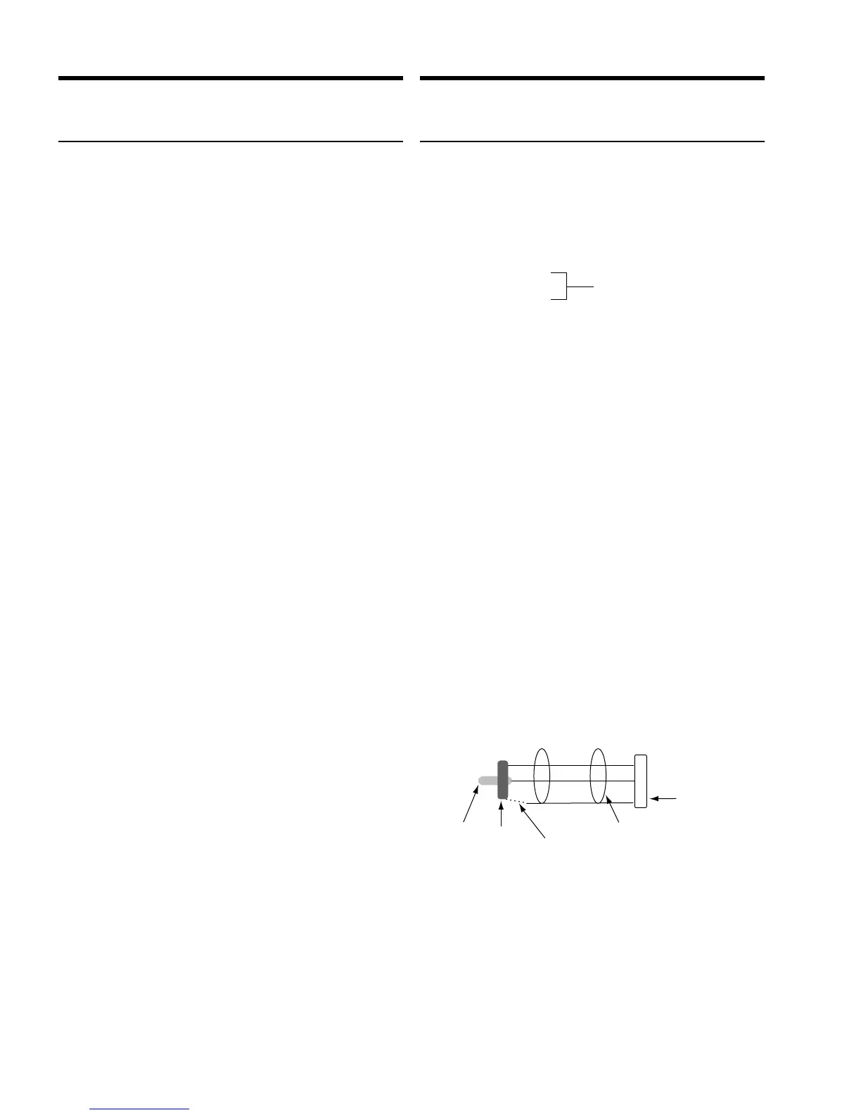
To connect an unbalanced audio source to the LD-1A,
use the following wiring connections:
LD-1A input
XLR
Connect shield to – terminal (ring
if the source equipment is floatin
Do not connect the shield if the
source is grounded.
chassis/eart
terminal
RCA output
jack
Tip is
positive
terminal
shield
Ring is
negative
terminal
+
–
–
3
2
1
••
Differential Inputs
LD-1A input
XLR
Connect shield to – terminal (ring)
if the source equipment is floating.
Do not connect the shield if the
source is grounded.
chassis/earth
terminal
RCA output
jack
Tip is
positive
terminal
shield
Ring is
negative
terminal
+
–
–
3
2
1
••
 Loading...