6
Mid-Hi Output
The Mid-Hi output has two switch-activated, optimized
filters. Pushing the Lo Cut switch in activates a high-
pass filter (160 Hz, Q = 0.8, –12 dB/octave) that performs
a crossover function for the Mid-Hi output. The filter is
bypassed with the switch out.
Pushing the Array EQ switch in activates a filter (6 dB cut
at 220 Hz, 0.6 octave bandwidth) to equalize the low-
mid rise produced by three to five horizontally arrayed
MSL-4s. The filter is bypassed with the switch out.
NOTE: The Array EQ filter compensates for MSL-4 array
characteristics in free-space. We recommend using the
Meyer SIM System II Sound Analyzer and CP-10 Paramet-
ric Equalizer to measure and correct problems caused by
the acoustical environment.
It is important to note that the Mid-Hi output produces a
full-range signal when both the Array EQ and Lo-Cut
filters are out (bypassed).
DS-2 and Sub Outputs
The DS-2 & Sub Crossover network, optimized for the
DS-2P and 650-P (or PSW-2), is composed of a low-pass
and an elliptical filter. Pushing the switch in activates
the two-way crossover, sending frequencies below 80 Hz
to the Sub output and above 80 Hz to the DS-2 output.
With the switch out, a full-range signal is sent to both the
DS-2 and Sub outputs. When the DS-2P is used alone as
a subwoofer, or is not included in the system, the switch
should be out.
NOTE: Full-range signals may be applied to Meyer self-
powered subwoofers because they have built-in active
crossovers that filter mid-hi frequencies; external cross-
overs are unnecessary.
The DS-2 and Sub outputs each have a polarity toggle
(DS-2 φ, Sub φ). With the switch out, the polarity is set to
0°. Pushing the switch in inverts the polarity 180° with
respect to the out position.
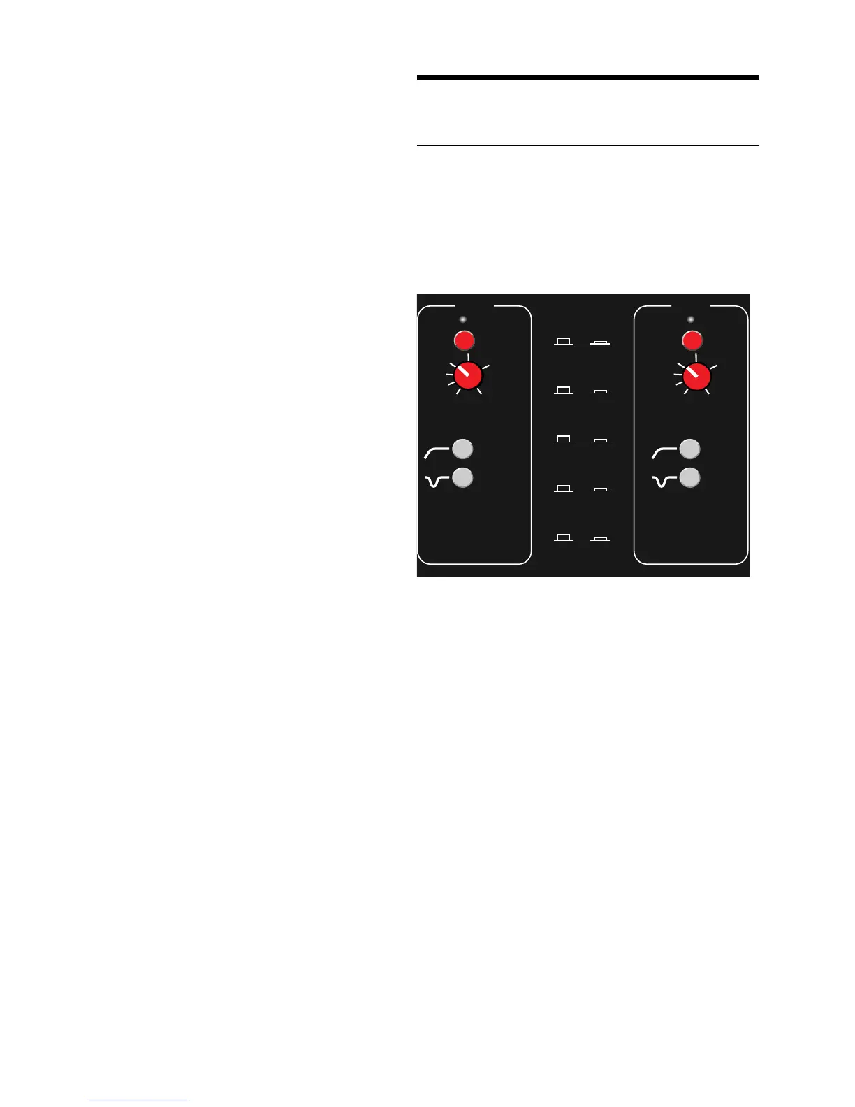
Auxiliary Channels 3-8
The six auxiliary channels 3–8 control down-fill, front-
fill, and delay systems. Each channel has a Signal/Mute-
Clip indicator, gain control, mute switch, and Lo Cut and
Array EQ filters, all of which are explained in the previous
section.
Channels 3–8 are identical; channels 4 and 5 are shown
below.
Mute
Signal Mute-Clip
CH 5
Mute
Signal Mute-Clip
CH 4
Out In
Sub DS-2 & Sub
Active Mute
0
180
φ Polarity
Mute
Crossover
Array EQ
Out In
Lo Cut
Array
EQ
Lo Cut
Master
Array
EQ
Lo Cut
Master
-12
-6
-3
0
+3
+6
-9
-12
-6
-3
0
+3
+6
-9
Auxiliary channels 4 and 5 with switch function summary.
The auxiliary channels can also divide the main system
into separate subsystems. For example:
1. Route the CH 1 input signal to CH 3 using the
CH 1 Loop connector.
2. Connect the CH 3 output to the outer two elements
of an array of five mid-hi speakers.
3. Connect the Mid-Hi output to the inner three
elements of the mid-hi array.
Using main and auxiliary channels to apply separate
levels for the edge and internal elements of a mid-hi
system is incorportated into an example configuration
on page 8.