7
Example Configurations
This section demonstrates the flexibility and utility of the
LD-1A with four example applications.
Speaker Placement and Polarity
The cabinets in the following example configurations are
in a close-proximity coplanar orientation, unless other-
wise stated. Placing speakers more than 5 feet apart may
require setting them to opposite polarities to compensate
for the propagation delay between speakers.
Measurement and Correction
Measurement and correction tools are required to as-
semble a complete sound system, particularly when the
venue requires precise array design, delay systems, or
compensation for significant reverberation. We recommend
using the Meyer SIM® System II Sound Analyzer and
CP-10 Parametric Equalizer to
• assist the process of choosing and configuring
speakers;
• measure propagation delays between subsystems
to set the correct polarity and delay times;
• measure and equalize variations in frequency
response caused by the acoustical environment
and the placement and interaction of speakers.
Contact Meyer Sound for assistance with your application.
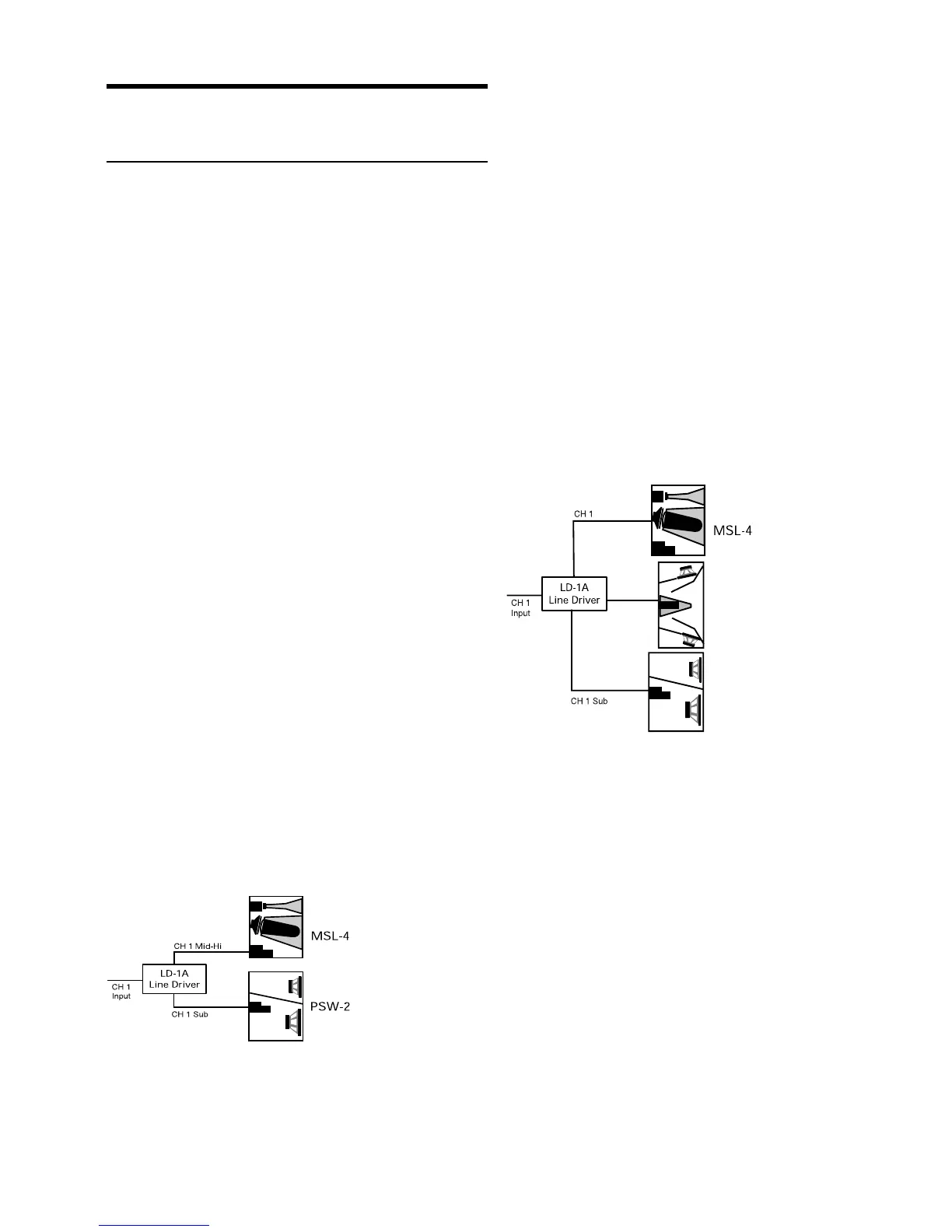
MSL-4 and PSW-2
The MSL-4 and PSW-2 form a compatible full-range
system. However, due to an overlap in LF ( low frequency)
response between the two speakers, there is a rise in the
system frequency response in the range 65–120 Hz. It is
important to emphasize that the speakers are in phase in
this region. The rise can be eliminated by activating the
Lo Cut filter for the Mid-Hi output, if desired.
Set the MSL-4 and PSW-2 to the same polarity.
Although a typical MSL-4:PSW-2 ratio is 2:1, the Sub and
Mid-Hi gain controls allow the ratio to vary while main-
taining control of the spectral balance of the system.
The 650-P can be used interchangeably with the PSW-2
but the 650-P’s larger size precludes tight-packing
configurations with the MSL-4; the 650-P also lacks
rigging hardware.
MSL-4, DS-2P, and 650-P
Adding the DS-2P to an MSL-4/650-P system enhances
LF power and clarity. With the DS-2 & Sub Crossover
switch in, the DS-2 and Sub outputs each receive signals
optimized for the frequency response capabilities of the
DS-2P and 650-P.
The MSL-4 is driven from the CH 1 Mid-Hi output with
the Lo Cut filter in to minimize the overlap in frequency
response with the DS-2P and 650-P. Set the 650-P to the
opposite polarity to the MSL-4 and DS-2P.
Mid-Hi
650-P
DS-2P/
DS-4P
DS-2
Set the 650-P to the opposite polarity to the DS-2P and
MSL-4.