5
AC POWER
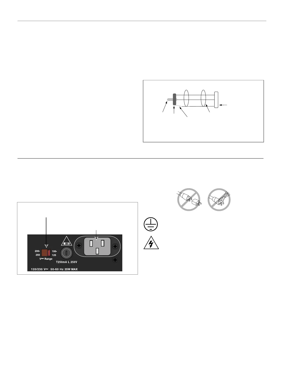
AC INLET AND VOLTAGE SELECT SWITCH
The LD-2 uses an international standard IEC 320 Mains AC
inlet. This convenient rear panel receptacle accepts many
power cord types for mains outlets used throughout the world.
The LD-2 must have the correct power cord for the AC power
in the area in which it will be used.
The LD-2 operates in two AC voltage ranges: 90 - 125V and
180 - 250V, at 50 or 60Hz. The voltage select switch on the
rear panel must be set to the proper voltage before applying
AC power. Connecting the LD-2 to a 225VAC source with the
voltage select switch in the 90 - 125V position could blow the
fuse. Unplug the power cord before changing the voltage
select switch!
The audio outputs are muted internally during normal power
on and off, and in case of sudden loss of AC power or
unstable line voltage. This precaution prevents noise
transmission, and possible damage, to interconnected devices.
Do not use a ground-lifting adapter or cut the AC
ground pin.
To avoid electrical shock and damage to the unit,
use the power cord specified by Meyer Sound or an
equivalent that satisfies the requirements of the
local safety testing agency. Do not operate the unit
if the power cables are frayed or broken.
AC FUSE
Always disconnect the power cord before changing the fuse.
To replace the fuse, insert a flat-blade screwdriver in the fuse
cap and gently turn counterclockwise; the fuse springs from
its socket. Replace only with a 5 x 20 mm, T 250 mA, 250 V,
time-lag fuse that conforms to identical safety agency
standards.
If the fuse blows again, contact Meyer Sound for repair
information.
IEC 320
male power inlet
Voltage select
switch
Figure 3 The LD-2’s dual voltage operation
AUDIO INPUT
The LD-2 presents a 10Ω balanced input impedance to a
three-pin XLR connector wired with the following convention:
Case — Earth (AC) ground and chassis
Pin 1 — Earth (AC) ground and chassis
Pin 2 — Signal
Pin 3 — Signal
The LD-2 is balanced in and out, and consequently has no hot
(+) pin. Pins 2 and 3 carry the input as a differential signal.
Use standard audio cables with XLR connectors for balanced
signal sources.
The audio input signal should always be applied between pins
2 and 3. Pin 1 is connected to the chassis which also
connects to earth ground through the AC cable. This allows
interference (EMI and ESD) coupled to the shield of the audio
cable to bleed back to earth ground. Therefore, pin 1 is a
noisy ground and audio signals should not be connected to
pin 1.
Most modern balanced audio sources (electronically balanced
or transformer output) conform to the wiring convention
previously described and interface correctly with the LD-2.
However, an audio source may produce noise if it connects pin
1 to a quiet internal audio ground, and is then connected to
pin 1 of the LD-2 (chassis/earth). To alleviate this noise, try
disconnecting pin 1 (or the cable shield) of the audio source.
To connect an unbalanced audio source to the LD-2, use the
wiring connections shown below:
LD-2 input
XLR
Connect shield to - terminal (ring)
if the source equipment is floating.
Do not connect the shield if the
source is grounded.
Chassis/Earth
terminal
RCA output
jack
Tip is
positive
terminal
Shield
Ring is
negative
terminal
+
-
-
3
2
1
ïï
Figure 2 Connecting the LD-2 to an unbalanced source
 Loading...